


Appendix B Accessories|
B-2 Revision Nov. 2008, VLE1, SW V1.03
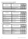
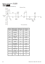
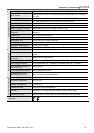
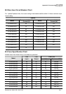
B.1 All Brake Resistors & Brake Units Used in AC Motor Drives
Applicable
Motor
Voltage
hp kW
Full Load
Torque
Nm
Resistor value spec
for each AC Motor
Drive
Brake Torque
10%ED
Min. Equivalent
Resistor Value for each
AC Motor Drive
7.5 5.5 3.111
2400W 16Ω
125
16Ω
10 7.5 4.148
3000W 12Ω
125
12Ω
15 11 6.186
4800W 9Ω
125
9Ω
20 15 8.248
4800W 6.8Ω
125
6.8Ω
25 18.5 10.281
6000W 6Ω
125
6Ω
30 22 12.338
9600W 5Ω
125
5Ω
40 30 16.497
6000W 5Ω
125
5Ω
230V Series
50 37 20.6
9600W 4Ω
125
4Ω
7.5 5.5 3.111
500W 50Ω
125
50Ω
10 7.5 4.148
1000W 40Ω
125
40Ω
15 11 6.186
1000W 33Ω
125
33Ω
20 15 8.248
1500W 25Ω
125
25Ω
25 18.5 10.281
4800W 21Ω
125
21Ω
30 22 12.338
4800W 19Ω
125
19Ω
40 30 16.497
6000W 20Ω
125
20Ω
50 37 20.6
9600W 16Ω
125
16Ω
60 45 24.745
9600W 13.6Ω
125
13.6Ω
75 55 31.11
12000W 10Ω
125
10Ω
460V Series
100 75 42.7
19200W 6.8Ω
125
6.8Ω
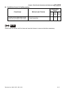
NOTE
1. Please select the recommended resistance value (Watt) and the duty-cycle value (ED%).
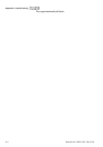
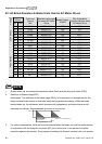
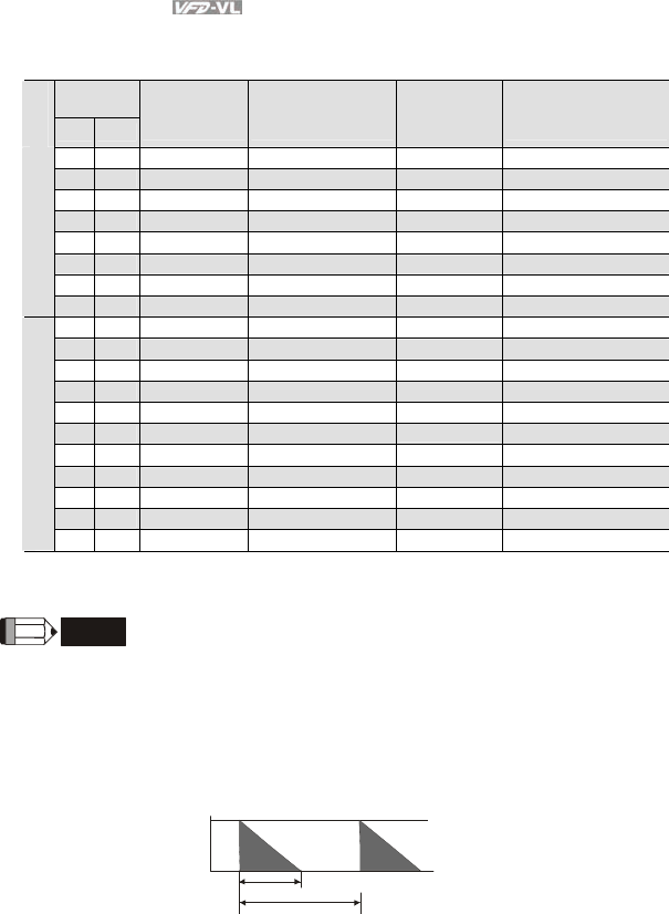
2. Definition for Brake Usage ED%
Explanation: The definition of the brake usage ED(%) is for assurance of enough time for the
brake unit and brake resistor to dissipate away heat generated by braking. When the brake
resistor heats up, the resistance would increase with temperature, and brake torque would
decrease accordingly. Recommended cycle time is one minute.
100%
T0
T1
Brake Time
Cycle Time
ED% = T1/T0x100(%)
3. For safety consideration, install an overload relay between the brake unit and the brake resistor.
In conjunction with the magnetic contactor (MC) prior to the drive, it can perform complete
protection against abnormality. The purpose of installing the thermal overload relay is to protect