


Chapter 4 Parameters|
4-92 Revision Nov. 2008, VLE1, SW V1.03
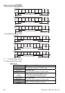
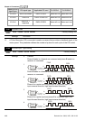
3.4 Check sum
ASCII mode:
LRC (Longitudinal Redundancy Check) is calculated by summing up, module 256, the values of
the bytes from ADR1 to last data character then calculating the hexadecimal representation of the
2’s-complement negation of the sum.
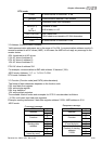
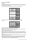
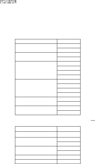
For example, reading 1 word from address 0401H of the AC drive with address 01H.
STX ‘:’
‘0’ Address 1
Address 0
‘1’
‘0’ Function 1
Function 0
‘3’
‘0’
‘4’
‘0’
Starting data address
‘1’
‘0’
‘0’
‘0’
Number of data
‘1’
‘F’ LRC Check 1
LRC Check 0
‘6’
CR END 1
END 0
LF
01H+03H+04H+01H+00H+01H=0AH, the 2’s-complement negation of 0AH is F6H.
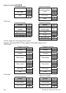
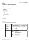
RTU mode:
Address
01H
Function 03H
21H Starting data address
02H
00H Number of data
(count by word)
02H
CRC CHK Low 6FH
CRC CHK High F7H
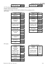
CRC (Cyclical Redundancy Check) is calculated by the following steps:
Step 1: Load a 16-bit register (called CRC register) with FFFFH.
Step 2: Exclusive OR the first 8-bit byte of the command message with the low order byte of the
16-bit CRC register, putting the result in the CRC register.
Step 3: Examine the LSB of CRC register.
Step 4: If the LSB of CRC register is 0, shift the CRC register one bit to the right with MSB zero
filling, then repeat step 3. If the LSB of CRC register is 1, shift the CRC register one bit to the right
with MSB zero filling, Exclusive OR the CRC register with the polynomial value A001H, then repeat
step 3.
Step 5: Repeat step 3 and 4 until eight shifts have been performed. When this is done, a complete
8-bit byte will have been processed.
Step 6: Repeat step 2 to 5 for the next 8-bit byte of the command message. Continue doing this
until all bytes have been processed. The final contents of the CRC register are the CRC value.
When transmitting the CRC value in the message, the upper and lower bytes of the CRC value
must be swapped, i.e. the lower order byte will be transmitted first.