


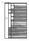

Chapter 4 Parameters|
Revision Nov. 2008, VLE1, SW V1.03 4-87
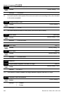
09-04 Communication Protocol
Control
mode
VF VFPG SVC FOCPG TQCPG FOCPM
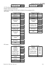
Factory Setting: 13
Settings 0 Modbus ASCII mode, protocol <7,N,1>
1 Modbus ASCII mode, protocol <7,N,2>
2 Modbus ASCII mode, protocol <7,E,1>
3 Modbus ASCII mode, protocol <7,O,1>
4 Modbus ASCII mode, protocol <7,E,2>
5 Modbus ASCII mode, protocol <7,O,2>
6 Modbus ASCII mode, protocol <8,N,1>
7 Modbus ASCII mode, protocol <8,N,2>
8 Modbus ASCII mode, protocol <8,E,1>
9 Modbus ASCII mode, protocol <8,O,1>
10 Modbus ASCII mode, protocol <8,E,2>
11 Modbus ASCII mode, protocol <8,O,2>
12 Modbus RTU mode, protocol <8,N,1>
13 Modbus RTU mode, protocol <8,N,2>
14 Modbus RTU mode, protocol <8,E,1>
15 Modbus RTU mode, protocol <8,O,1>
16 Modbus RTU mode, protocol <8,E,2>
17 Modbus RTU mode, protocol <8,O,2>
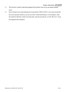
1. Control by PC or PLC
A VFD-VL can be set up to communicate on Modbus networks using one of the following modes:
ASCII (American Standard Code for Information Interchange) or RTU (Remote Terminal Unit).
Users can select the desired mode along with the serial port communication protocol in Pr.09-04.
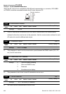
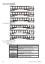
Code Description:
ASCII mode:
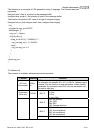
Each 8-bit data is the combination of two ASCII characters. For example, a 1-byte data:
64 Hex, shown as ‘64’ in ASCII, consists of ‘6’ (36Hex) and ‘4’ (34Hex).
Character ‘0’ ‘1’ ‘2’ ‘3’ ‘4’ ‘5’ ‘6’ ‘7’
ASCII code 30H 31H 32H 33H 34H 35H 36H 37H
Character ‘8’ ‘9’ ‘A’ ‘B’ ‘C’ ‘D’ ‘E’ ‘F’
ASCII code 38H 39H 41H 42H 43H 44H 45H 46H
RTU mode:
Each 8-bit data is the combination of two 4-bit hexadecimal characters. For example, 64
Hex.
2. Data Format