


Chapter 3 Operation and Start Up|
Revision Nov. 2008, VLE1, SW V1.03 3-13
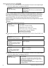
3.3.2.5 Step 5
Trial run
This step is used to trial run after finishing the settings of Step 1 to Step 4 to check if it runs
normally after executing the inspection with the loaded motor. At the same time, please also
check if the operations of multi-function output terminals is normal, such as the action of
the brake release and electromagnetic valve correspond to the host controller.
It needs to check the switch between each step speed, current value, the noise in the
carriage and noise source during operation.
3.3.2.6 Step 6
Elevator tuning
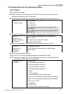
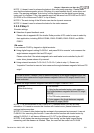
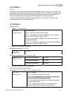
1. Setting Pr. 11-00 to bit 0=1
Pr.11-00
System control
Bit 0=0: disable
Bit 0=1: ASR Auto tuning, PDFF enable
Bit 7=1: When position control is enabled, it doesn’t need to
set Pr.07-02 (DC Brake Current Level)
Bit 15=0: when power is applied, it will detect the position of
magnetic field again
Bit 15=1: when power is applied, it will start from the magnetic
field position of previous power failure
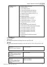
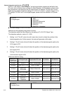
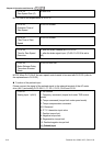
2. Smooth test for general operation
Adjust the setting of Pr.11-05
Pr.11-05
Inertial Ratio
1~300%
Adjust the settings of Pr.11-06 to Pr.11-08
Zero-speed Bandwidth 0~40Hz
Low-speed Bandwidth 0~40Hz
Settings of Pr.11-
06 to Pr.11-08
High-speed Bandwidth 0~40Hz
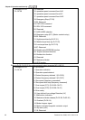
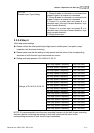
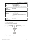
3. Start-up adjustment (only for PM motor)
Control by the zero-speed position
Setting Pr.11-00, 10-19, 10-22, 10-23, 02-29 and 10-24
Pr.11-00
System control
Bit 0=0: disable
Bit 0=1: ASR Auto tuning, PDFF enable
Bit 7=1: When position control is enabled, it doesn’t need
to set Pr.07-02 (DC Brake Current Level)
Bit 15=0: when power is applied, it will detect the position
of magnetic field again
Bit 15=1: when power is applied, it will start from the
magnetic field position of previous power failure