


Chapter 4 Parameters|
4-102 Revision Nov. 2008, VLE1, SW V1.03
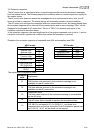
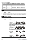
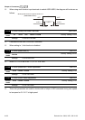
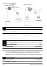
When using multi-function input terminals to switch ASR1/ASR2, the diagram will be shown as
follows.
ON
OFF
ASR 1
0.1 sec
OFF
0.1 sec
ASR 1
ASR 2
Setting multi-function input terminal to 17
(ASR1/ASR2 switch)
10-18 ASR Primary Low Pass Filter Gain Unit: 0.001
Control
mode
VF VFPG SVC FOCPG FOCPM
Factory Setting: 0.008
Settings 0.000 to 0.350 sec
It defines the filter time of the ASR command.
When setting to 1, this function is disabled.
10-19 Zero Speed Gain (P) Unit: 0.01
Control
mode
FOCPM
Factory Setting: 80.00
Settings 0.00 to 655.00%
When Pr.11-00 is set to Bit 7=1, Pr.10-19 is valid.
10-20 Zero Speed/ASR1 Width Adjustment Unit: 0.01
Control
mode
VFPG FOCPG FOCPM
Factory Setting: 5.00
Settings 0.0 to 120.00Hz
10-21 ASR1/ASR2 Width Adjustment Unit: 0.01
Control
mode
VFPG FOCPG FOCPM
Factory Setting: 5.00
Settings 0.0 to 120.00Hz
These two parameters are used to decide width of slope of ASR command during zero speed
to low speed or Pr.10-17 to high speed.