


Chapter 4 Parameters|
4-48 Revision Nov. 2008, VLE1, SW V1.03
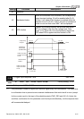
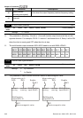
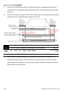
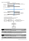
When the AC motor drive runs after Pr.02-29 delay time, the corresponding multi-function
output terminal (12: mechanical brake release) will be ON. This function should be used with
DC brake.
When the AC motor drive stops 12 after Pr.02-30 delay time, the corresponding multi-function
output terminal (12: mechanical brake release) will be OFF.
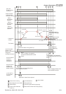
Motor speed/
Output frequency
07-03
DC brake
time during
start-up
07-04
DC brake
time during
stopping
Multi-function output
(m echani ca l br ake r ele as e)
Pr.02- 11 to 02-22=1 2
Mechanical brake
bounce time of mechani cal brake
RUN/STOP
02-29 Brake release delay time
when elevator starts
RUN STOP
02-30 Brake engage
delay time when
elevator stops
DC brake DC brake
Mechanical brake release
brake
engage
brake
engage
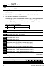
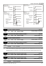
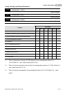
02-31 Turn On Delay of Magnetic Contact between Drive and Motor Unit:0.001
02-32 Turn Off Delay of Magnetic Contact between Drive and Motor Unit:0.001
Control
mode
VF VFPG SVC FOCPG TQCPG FOCPM
Factory setting:
0.200
Settings 0.000~65.000 Sec
After running, it is used with setting 40 of multifunction input terminal and settings 15 of
multifunction output terminals. When multifunction output terminals is ON, the drive starts
output after Pr.02-31 delay time. When drive stops output, multifunction output terminals will
release after Pr.02-32 delay time.