


Appendix B Accessories|
Revision Nov. 2008, VLE1, SW V1.03 B-35
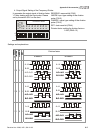
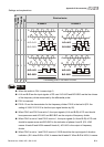
NOTE
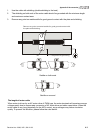
When the switch is ON, it means logic 0.
A-/A and B-/B are the input signals of PG card. A/O-/A/O and B/O-/B/O are the line driver
outputs of the frequency divider measured by the differential probe.
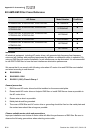
Bit 0-4 are the denominators for the frequency divider. Bit 0 is the low bit (EX: the setting
of 10110 is that the input signal divides by 13).
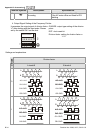
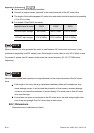
When the output pulse type of frequency divider is set to 0, A/O-/A/O, B/O-/B/O, OA-GND
and OB-GND are the outputs of frequency divider.
When the output pulse type of frequency divider is set to 1, B/O-/B/O and OB-GND are
the indication of phase A and B. (EX: LOW means A leads B and HIGH means B leads A).
A/O-/A/O and OA-GND are the output of frequency dividers.
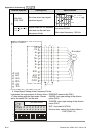
When changing the denominator of the frequency divider or output type, it needs to clear
the counter value by clock reset bit before operation.