


Appendix B Accessories|
Revision Nov. 2008, VLE1, SW V1.03 B-45
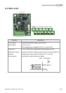
Descriptions
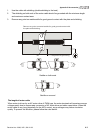
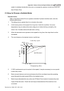
1. When the power +24VDC is applied to S1 and S2 (S1 is +), the relay contacts of S3 and S4 are
ON. When the power +24VDC isn’t applied to S1 and S2, the relay contacts of S3 and S4 are
OFF. At the meanwhile, EMVL-ASF01 can stop the output of the AC motor drive by connecting
to JP19 on the control board. It can also be used with MI8 to achieve two safety-loop
protections via hardware.
2. Multifunction input MI8
(1) Please remove JP1 from the control board before using safety-loop function. At the
meanwhile, the multifunction input MI8 can control the output of the AC motor drive.
(2) operation method:
MI8 is ON: the AC motor drive can output
MI8 is OFF: the AC motor drive can’t output
NOTE: Please insert JP1 into the control board when this function is disabled.
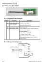
3. Safety-Relay EMVL-SAF01
(1) Please connect the power of J3 to JP19 on the control board and remove JP18 on the
control board.
(2) Operation method:
When the power is applied to S1-S2: It is ON and the AC motor drive can output
When the power isn’t applied to S1-S2: it is OFF and the AC motor drive can’t output
(3) S3-S4 are the monitor contacts and user can check the safety-loop by this contact.
NOTE
Please notice that when J3 of relay board is connected to JP19 of control board, JP18
must be removed when using EMVL-SAF01.
Please supply the power +24VDC to S1 and S2 before the AC motor drive is powered on
to drive relay.