


Chapter 4 Parameters|
Revision Nov. 2008, VLE1, SW V1.03 4-27
Setting 8: To increase torque and control speed precisely. (1:1000). This setting is only for
using with permanent magnet motor and others are for induction motor.
00-10
Reserved
00-11
Reserved
00-12
Carrier Frequency
Unit: 1
Control
mode
VF VFPG SVC FOCPG TQCPG FOCPM
Factory setting: 12
Settings 2~15KHz
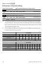
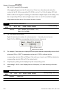
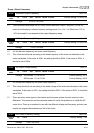
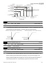
This parameter determinates the PWM carrier frequency of the AC motor drive.
230V/460V Series
Models
7.5-15HP
5.5-11kW
20-30HP
15-22kW
40-60 HP
30-45kW
40-100HP
30-75kW
Setting Range 2~15kHz 2~15kHz 02-09kHz 02~15kHz
Factory Setting 12kHz 9kHz 6kHz 6kHz
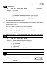
2kHz
8kHz
15kHz
Carrier
Frequency
Acoustic
Noise
Electromagnetic
Noise or Leakage
Current
Heat
Dissipation
Current
Wave
Significant
Minimal
Minimal
Minimal
Significant
Significant
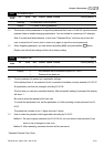
From the table, we see that the PWM carrier frequency has a significant influence on the
electromagnetic noise, AC motor drive heat dissipation, and motor acoustic noise.
00-13
Auto Voltage Regulation (AVR) Function
Control
mode
VF VFPG SVC FOCPG TQCPG FOCPM
Factory setting: 0
Settings 0 Enable AVR
1 Disable AVR
2 Disable AVR when deceleration stop
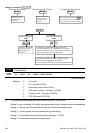
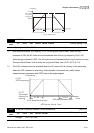
It is used to select the AVR mode. AVR is used to regulate the output voltage to the motor. For
example, if V/f curve is set to AC200V/50Hz and the input voltage is from 200 to 264VAC, the
output voltage won’t excess AC200V/50Hz. If the input voltage is from 180 to 200V, the output
voltage to the motor and the input voltage will be in direct proportion.
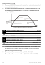
When setting Pr.00-13 to 1 during ramp to stop and used with auto accel./decel. function, the
acceleration will be smoother and faster.