


Chapter 4 Parameters|
4-60 Revision Nov. 2008, VLE1, SW V1.03
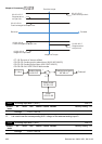
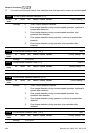
When the asynchronous motor is driven by the drive, the load and slip will be increased. This
parameter can be used to correct frequency and lower the slip to make the motor can run near
the synchronous speed under rated current. When the output current is larger than the motor
no-load current, the drive will compensate the frequency by Pr.05-13 setting. If the actual
speed is slower than expectation, please increase the setting and vice versa.
It is only valid in SVC mode.
05-14 Slip Deviation Level Unit: 1
Control
mode
VFPG SVC FOCPG
Factory setting: 0
Settings 0 to 1000% (0: disable)
05-15 Detection time of Slip Deviation Unit: 0.1
Control
mode
VFPG SVC FOCPG
Factory setting: 1.0
Settings 0.0 to 10.0 sec
05-16 Over Slip Treatment
Control
mode
VFPG SVC FOCPG
Factory setting: 0
Settings 0 Warn and keep operation
1 Warn and ramp to stop
2 Warn and coast to stop
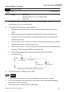
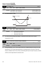
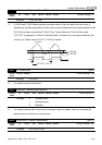
Pr.05-14 to Pr.05-16 are used to set allowable slip level/time and over slip treatment when the
drive is running.
05-17 Hunting Gain Unit: 1
Control
mode
VF VFPG SVC
Factory setting: 2000
Settings 0 to 10000 (0: disable)
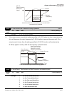
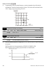
The motor will have current wave motion in some specific area. It can improve this situation by
setting this parameter. (When it is high frequency or run with PG, Pr.05-17 can be set to 0.
when the current wave motion happens in the low frequency, please increase Pr.05-17.)
05-18 Accumulative Motor Operation Time (Min.) Unit: 1
Control
mode
VF VFPG SVC FOCPG TQCPG
Factory setting: 00
Settings 00 to1439