


Chapter 4 Parameters|
4-94 Revision Nov. 2008, VLE1, SW V1.03
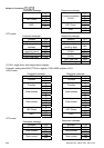
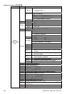
Content Address Function
Bit 12
1: disable bit 06-11
00B: No function
01B: operated by digital keypad
02B: operated by Pr.00-15 setting
Bit 13~14
03B: change operation source
Bit 15 Reserved
2001H Frequency command
Bit 0 1: EF (external fault) on
Bit 1 1: Reset
Bit 2 1: B.B. ON
2002H
Bit 3-15 Reserved
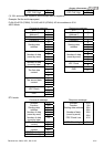
2100H Fault code: refer to Pr.06-16 to Pr.06-21
00: Stop
01: deceleration
10: Ready for operation
Bit 0-Bit 1
11: operation
Bit 2 1:JOG command
00: FWD command, FWD output
01: FWD command, REV output
10: REV command, FWD output
Bit 3-Bit 4
11: Reserved
Status
monitor Read
only
Bit 5 Reserved
Bit 6 Reserved
Bit 7 Reserved
Bit 8
1: Master frequency Controlled by communication
interface
Bit 9 1: Master frequency controlled by analog/external
terminals signal
Bit 10
1: Operation command controlled by
communication interface
Bit 11 1: Parameters have been locked
Bit 12 1: enable to copy parameter from keypad
2119H
Bit 13-15 Reserved
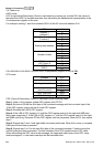
2102H Frequency command (F)
2103H Output frequency (H)
2104H Output current (AXXX.X)
2105H DC-BUS Voltage (UXXX.X)
2106H Output voltage (EXXX.X)
2107H Current step number of Multi-Step Speed Operation
2116H Multi-function display (Pr.00-04)
2201H Pr.00-05 user-defined setting
2203H AUI1 analog input (XXX.XX %)
2204H ACI analog input (XXX.XX %)
2205H AUI2 analog input (XXX.XX %)
2206H Display temperature of IGBT (
o
C)
2207H Display temperature of heatsink (
o
C) (only for model 40HP
and above)
2208H Digital input state
2209H Digital output state