


Chapter 4 Parameters|
Revision Nov. 2008, VLE1, SW V1.03 4-53
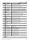
It is used to set the corresponding ACI voltage of the external analog input 0.
03-05 Analog Input Bias 1 (AUI2) Unit: 0.1
Control
mode
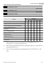
VF VFPG SVC FOCPG TQCPG FOCPM
Factory setting: 0.0
Settings -100.0~100.0%
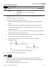
It is used to set the corresponding AUI2 voltage of the external analog input 0.
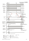
The relation between external input voltage/current and setting frequency is equal to -10~+10V
(4-20mA) corresponds to 0-60Hz.
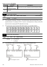
03-06 Positive/negative Bias Mode (AUI1)
Control
mode
VF VFPG SVC FOCPG TQCPG FOCPM
Factory setting: 0
03-07 Positive/negative Bias Mode (ACI)
Control
mode
VF VFPG SVC FOCPG TQCPG FOCPM
Factory setting: 0
03-08 Positive/negative Bias Mode (AUI2)
Control
mode
VF VFPG SVC FOCPG TQCPG FOCPM
Factory setting: 0
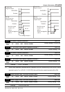
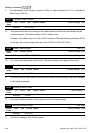
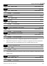
Settings 0 Zero bias
1 Lower than bias=bias
2 Greater than bias=bias
3 The absolute value of the bias voltage while serving as the center
4 Serve bias as the center
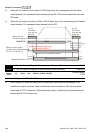
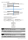
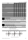
In a noisy environment, it is advantageous to use negative bias to provide a noise margin. It is
recommended NOT to use less than 1V to set the operating frequency.
03-09 Analog Input Gain 1 (AUI1) Unit: 0.1
Control
mode
VF VFPG SVC FOCPG TQCPG FOCPM
Factory setting: 100.0
03-10 Analog Input Gain 1 (ACI) Unit: 0.1
Control
mode
VF VFPG SVC FOCPG TQCPG FOCPM
Factory setting: 100.0
03-11 Analog Input Gain 1 (AUI2) Unit: 0.1
Control
mode
VF VFPG SVC FOCPG TQCPG FOCPM
Factory setting: 100.0
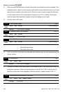
Settings -500.0~500.0%