


HYDRA
Service Manual
2A-18
description of the External Trigger operation may be found in the "External Trigger
Input Circuits" section.
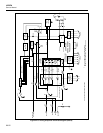
2A-40. RS-232 Interface
The RS-232 interface is composed of connector A1J4, RS-232 Driver/Receiver A1U13,
and the serial communication hardware in Microprocessor A1U1.
The serial communication transmit signal (A1U1-80) goes to the RS-232 driver (A1U13-
14), where it is inverted and level shifted so that the RS-232 transmit signal transitions
between approximately +5.0 and -5.0V dc. When the instrument is not transmitting, the
driver output (TP13;A1U13-3) is approximately -5.0V dc. The RS-232 receive signal
from A1J4 goes to the RS-232 receiver A1U13-4, which inverts and level shifts the
signal so that the input to the serial communication hardware transitions between 0 and
+5.0V dc. When nothing is being transmitted to the instrument, the receiver output
(TP12;A1U13-13) is +5.0V dc.
Data Terminal Ready (DTR) and Request To Send (RTS) are modem control signals
controlled by the Microprocessor. When the instrument is powered up, the
Microprocessor initially sets DTR and RTS false by setting A1U1-61 and A1U1-79 high,
which results in the RS-232 driver outputs (A1U13-7 and A1U13-5 respectively) going
to -5.0V dc. When the instrument has initialized the RS-232 interface and is ready to
receive and transmit, A1U1-61 and A1U1-79 will go low, resulting in the RS-232 DTR
and RTS signals going to +5.0V dc. The RS-232 DTR and RTS signals will remain at
+5.0V dc until the instrument is powered down except for a short period of time when
the user changes RS-232 communication parameters from the front panel of the
instrument.
Clear To Send (CTS) and Data Set Ready (DSR) are modem control inputs from the
attached RS-232 equipment. Of these signals, only CTS is used when CTS flow control
is enabled when CTS is turned on via the RS-232 communication setup menu. The CTS
modem control signal from A1J4 goes to the RS-232 receiver A1U13-6, which inverts
and level shifts the signal so that the input to the Microprocessor (A1U1-51) transitions
between 0 and +5.0V dc. When the instrument is cleared to send characters to the RS-
232 interface, the receiver output (A1U13-11) is +5.0V dc. If the RS-232 CTS signal is
not driven by the attached RS-232 equipment, the receiver output (A1U13-11) is near 0V
dc.
2A-41. Option Interface
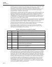
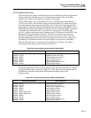
The interconnection to the option slot is implemented by J1 on the Main PCA. This
connector (A1J1) routes the outguard logic power supply (VCC and GND), eight bits of
the data bus (D<8> through D<15>), RDU*, WRU*, OCLK, RESET*, OPTE*, and the
lower three bits of the address bus to the hardware installed in the option slot. This
connector also routes an interrupt signal (OINT*) from the option hardware to the IRQ1*
input of the Microprocessor (A1U1-97). The OPTE*, RDU*, and WRU* signals pass
through series resistors that are necessary to ensure that the instrument meets EMI/EMC
performance requirements.
An option sense signal from the installed option allows the Microprocessor to detect
whether or not option hardware is installed. Currently there is no optional hardware
available for this instrument.