


Performance Testing and Calibration
Calibration
4
4-25
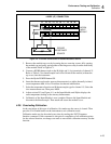
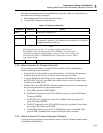
1211 13 14 15 16 17 18 19 20
21 345678910
SOURCE
(4-WIRE)
SENSE
(4-WIRE)
H L H LH LH LH LH LH LH LH LH L
H L H LH LH LH LH LH LH LH LH L
4-WIRE (4T) CONNECTION
DECADE
RESISTANCE
SOURCE
HYDRA
INPUT
MODULE
s30f.eps
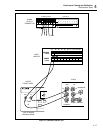
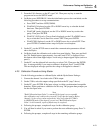
Figure 4-5. 4-Terminal Connections to Decade Resistance Source
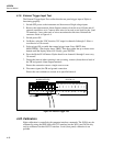
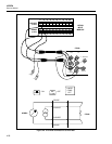
3. Remove the module top cover by loosening the two securing screws, fully opening
the module top and gently prying either of the hinge ears away from the main body
of the module. Refer to Figure 4-1.
4. Connect a KNBS thermocouple to the H (high) and L (low) terminals of channel 15.
Refer to Table 4-3 for thermocouple lead colors. Reinstall the module (without the
top cover) into the instrument.
5. Press the Hydra POWER button ON.
6. Insert the thermocouple and a mercury thermometer in a stable, thermally-isolated,
room-temperature bath. Allow 20 minutes for thermal stabilization.
7. Select the temperature function and K thermocouple type for channel 15. Select the
slow measurement rate. Then press MON.
8. Adjust resistor R3 (see Figure 4-1) on the Input Module until Hydra displays the
same temperature reading as the mercury thermometer.
9. Calibration of the Input Module is now complete. Remove the Input Module and
disconnect the thermocouple. Then attach and secure the module cover.
4-29. Concluding Calibration
At the conclusion of this type of calibration, first make sure the source is cleared. Then
press the CAL Enable button on the instrument to exit calibration mode.
Calibration mode can also be exited at any time by sending the *RST Computer
Interface command. If this command is sent prior to completion of all calibration points
for the selected function, no changes are made to nonvolatile calibration memory for that
function.