


HYDRA
Service Manual
5-20
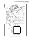
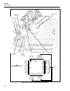
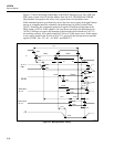
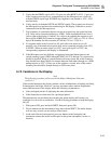
Figure 5-7 shows the timing relationships of the 6303Y Microprocessor lines LIR* and
WR* to the system clock (E) and the address lines A0..A15. The ROM and NVRAM
Chip Enables correspond to the active (low) region shown for the address lines.
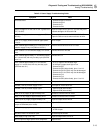
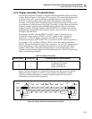
If the instrument powers up without any errors, but does not recognize front-panel button
presses or computer interface commands, the problem may be in the Counter/Timer
(A1U2). Normally, this component generates a regular 50-millisecond interrupt at the
IRQ* output (A1U2-9). If this output is low (and never goes high), the Microprocessor
(A1U4) is failing to recognize the interrupt or the microprocessor interface to A1U2 is
not working correctly. Also check output A1U2-6 for a 10-Hz square wave. If this output
is not correct, check for the E clock at A1U2-17, and verify the microprocessor interface
signals (CNTR*, D0 .. D7, A0 .. A2, R/W*, and RESET*.)
E
2.4V
AD
t
0.8V
PW
PW
PW
t
cyc
EL
EH
tt
t
t
t
t
t
t
tt
t
t
t
Ef
AH1
2.4V
0.8V
AH2
HRW
RW
2.4V
0.8V
t
RWD
DDW
HW2
HW1
2.4V
0.8V
DSR
ACC
HR
HLR
DLR
2.0V
0.8V
0.8V
A
0
~
R/W
RD,WR
MCU Read
MCU Write
D
0
~
D
7
D
0
~
D
7
LIR
A
15
,
Er
s38f.eps
Figure 5-7. Microprocessor Timing