


Diagnostic Testing and Troubleshooting (2635A)
Analog Troubleshooting
5A
5A-13
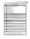
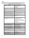
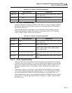
Table 5A-3. Power Supply Troubleshooting Guide (2635A) (cont)
Symptom Fault
A1U18 hot. Shorted A1C32
A1U18 oscillates. Open A1C32.
A1U19 oscillates. Open A1C34.
A1U19 very hot. - Shorted A1U22 (VCC to VSS).
- Shorted A1U23 (VCC to VSS).
A1U19 hot. Shorted A1C34.
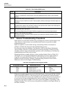
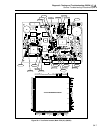
Check the inguard supply voltages on the A/D Converter PCA with respect to A3TP9.
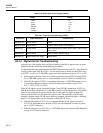
The following table lists the components nearest the power supply test points.
Power Supply Nearest Component Acceptable Range
VDD
VSS
VDDR
+VAC
-VAC
A3C8
A3C9
A3C19
A3CR1
A3C26
5.00 to 5.70V dc
-5.10 to -5.75V dc
5.30 to 5.95V dc
4.7 to 5.7V dc
-4.8 to -5.7V dc
Check that the inguard Microcontroller A3U9 RESET* line is de-asserted. Check VDD
at A3TP1, referenced to A3TP9.
Check that the microcontroller crystal oscillator is running. When measured with a high
input impedance oscilloscope or timer/counter, the oscillator output at A3TP10 should
be a 3.6864-MHz sine wave (271.3 ns period), and the divided-down E clock output at
A3U9 pin 68 should be a 921.6 kHz-square wave (1.085 µs period).
Check outguard to inguard communication. Setup an input channel and enable monitor
measurements on that channel, causing the outguard to transmit to the inguard
approximately every 10 seconds.
On the Main PCA, look for outguard-to-inguard communication (5.0V (VCC) to near 0V
pulses) at A1TP15, referenced to A1TP1. On the A/D Converter PCA, check for 5.35V
(VDD) to near 0V pulses at A3TP8, referenced to A3TP9.
At the start of outguard-to-inguard communication, the A/D Microcontroller (A3U9)
should be RESET. Check for this reset pulse (5.35V (VDD) to near 0V, lasting
approximately 1 millisecond) on A3TP1 with respect to A3TP9.
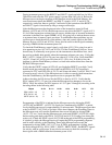
Check for the following inguard-to-outguard communication activity:
PCA Test Point To Pulses
A/D Converter
Main
A3TP7
A1TP8
A3TP9
A1TP1
5.55V (VDDR) to 0.7V
5.0V dc (VCC) to 0.0V