


Diagnostic Testing and Troubleshooting (2635A)
Memory Card I/F PCA (A6) Troubleshooting.
5A
5A-31
5A-28. Failure to Detect Insertion of Memory Card
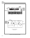
When a Memory Card is inserted into the Memory Card Interface, the card detect signals
(CD1 and CD2; A6U1-19 and A6U1-21) are driven low. Verify that the Memory Card
Controller detects this and interrupts the Microprocessor (A1U1) by driving the
MCINT* signal (A6U1-60) low. Failure to generate the interrupt may be due to
problems with the data bus (D8..D15), the address bus (A1..A4), or one of the control
signals (XSCLK, XMCARD*, XWRU*, XRDU*, and RESET*). Consult the schematics
found in Section 8 of this manual and verify these interconnections. Consider the ribbon
cable that connects the Main Assembly (A1) to the Memory Card Interface Assembly
(A6) as a possible source of the problem as well. It may be necessary to repeatedly insert
and remove the card to observe the behavior of these signals.
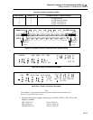
5A-29. Failure to Power Card / Illuminate the Busy Led
When a Memory Card is properly inserted and then detected by the Microprocessor
(A1U1), the Memory Card should be powered up and the BUSY LED should be
illuminated for a short period of time. If the BUSY LED is not visibly illuminated when
the card is inserted, verify the following things using a storage oscilloscope. Verify that
the gate of transistor A6Q1 is driven low by A6U1-26 (check both ends of resistor
A6R13). When the gate of A6Q1 is near 0 volts dc, the drain of transistor (A6Q1-5
through A6Q1-8) should be near 5 volts dc.
Approximately 50 milliseconds after the transistor drain pins (A6Q1-5 through A6Q1-8)
go to about 5 volts dc, the BUSY LED should be turned on by A6U1-25 going low to
sink current through the LED (A6DS1) and current limiting resistor (A6R10). When the
Microprocessor (A1U1) is done accessing data on the memory card, A6U1-25 and
A6U1-26 will both go high again to turn off the BUSY LED and the card power supply.
If the 50 millisecond delay between the memory card power being turned on and the
BUSY LED being turned on may be extended up to a total of 250 milliseconds if the
RDY/BSY signal (A6U1-23) is being held low by the memory card.
5A-30. Failure to Illuminate the Battery Led
The yellow BATTERY LED is controlled by a Memory Card Controller output (A6U1-
24). The Microprocessor checks the BVD1 and BVD2 outputs (A6U1-18 and A6U1-20
respectively) from the memory card about 50 milliseconds after it is powered up. The
BATTERY LED is turned on by A6U1-24 going low to sink current through the LED
(A6DS2) and current limiting resistor (A6R11).
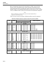
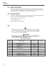
Verify that the BATTERY LED state matches the state of the BVD1 and BVD2 signals
as shown in the following table (H = 5 volts dc, L = 0 volts dc).
Battery LED BVD1 BVD2
Off
On
On
On
H
H
L
L
H
L
H
L