HYDRA
Service Manual
4-14
Send the following commands to Hydra in sequence, and measure that the correct
Digital Output line measures greater than +3.8V dc (HIGH state.)
DO_LEVEL 0,1 <CR>
Verify that output 0 measures a HIGH state.
DO_LEVEL 1,1 <CR>
Verify that output 1 measures a HIGH state.
Repeat the command for all eight outputs.
4-15. Digital Input Test
1. Perform the DIGITAL OUTPUT TEST steps 1 through 5.
2. Using either a terminal or a computer running a terminal emulation program, read
the Hydra Digital Input lines.
Send the following command to Hydra:
DIO_LEVELS? <CR>
Verify that the returned value is 255.
Note
The number returned is the decimal equivalent of the Digital Input binary
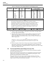
word (status of inputs 0 through 7). See Table 4-7 to determine if the
number returned corresponds to the inputs jumpered to ground in this
test.
3. Jumper input 0 to ground by connecting the ground test lead to the input 0 test lead.
Then send the following command to Hydra:
DIO_LEVELS? <CR>
Verify that the returned value is 254.
4. Disconnect input 0 from ground, then jumper input 1 to ground.
Send the command: DIO_LEVELS? <CR>
Verify that the returned value is 253.
5. Repeat step 4 for each input and verify the correct returned value (See Table 4-7).
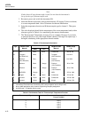
Table 4-7. Digital Input Values
Terminal Grounded State of Digital Inputs Decimal Value
none
0
1
2
3
4
5
6
7
Inputs 0-7, all HIGH
Inputs 1-7 HIGH, input 0 LOW
Inputs 0,2-7 HIGH, input 1 LOW
Inputs 0-1 and 3-7 HIGH, input 2 LOW
Inputs 0-2 and 4-7 HIGH, input 3 LOW
Inputs 0-3 and 5-7 HIGH, input 4 LOW
Inputs 0-4 and 6-7 HIGH, input 5 LOW
Inputs 0-5 and 7 HIGH, input 6 LOW
Inputs 0-6 HIGH, input 7 LOW
255
254
253
251
247
239
223
191
127
4-16. Totalizer Test
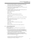
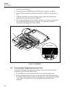
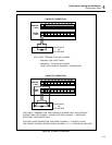
This totalizer verification test requires toggling Digital Output line 0 and using it as the
Totalizer input. The test requires computer interfacing with a host (terminal or


