Contents
(continued)
iii
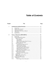
2A-22. Main PCA ........................................................................................ 2A-7
2A-23. Power Supply Circuit Description............................................... 2A-8
2A-31. Digital Kernel .............................................................................. 2A-10
2A-42. Digital I/O.................................................................................... 2A-18
2A-43. Digital Input Threshold ............................................................... 2A-19
2A-44. Digital Input Buffers.................................................................... 2A-19
2A-45. Digital and Alarm Output Drivers............................................... 2A-19
2A-46. Totalizer Input ............................................................................. 2A-19
2A-47. External Trigger Input Circuits ................................................... 2A-20
2A-48. A/D Converter PCA......................................................................... 2A-20
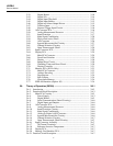
2A-49. Analog Measurement Processor.................................................. 2A-20
2A-50. Input Protection ........................................................................... 2A-23
2A-51. Input Signal Conditioning ........................................................... 2A-24
2A-57. Passive and Active Filters ........................................................... 2A-29
2A-58. A/D Converter ............................................................................. 2A-29
2A-59. Inguard Microcontroller Circuitry............................................... 2A-31
2A-60. Channel Selection Circuitry ........................................................ 2A-31
2A-61. Open Thermocouple Check......................................................... 2A-31
2A-62. Input Connector PCA....................................................................... 2A-32
2A-63. Display PCA .................................................................................... 2A-32
2A-64. Main PCA Connector .................................................................. 2A-32
2A-65. Front Panel Switches ................................................................... 2A-33
2A-66. Display......................................................................................... 2A-33
2A-67. Beeper Drive Circuit.................................................................... 2A-33
2A-68. Watchdog Timer and Reset Circuit............................................. 2A-34
2A-69. Display Controller ....................................................................... 2A-34
2A-70. Memory Card Interface PCA........................................................... 2A-37
2A-71. Main PCA Connector .................................................................. 2A-37
2A-72. Microprocessor Interface............................................................. 2A-37
2A-73. Memory Card Controller ............................................................. 2A-37
2A-74. PCMCIA Memory Card Connector............................................. 2A-39
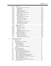
3 General Maintenance......................................................................... 3-1
3-1. Introduction ........................................................................................ 3-3
3-2. Warranty Repairs and Shipping .......................................................... 3-3
3-3. General Maintenance ........................................................................... 3-3
3-4. Required Equipment ....................................................................... 3-3
3-5. Power Requirements ....................................................................... 3-3
3-6. Static Safe Handling ....................................................................... 3-3
3-7. Servicing Surface-Mount Assemblies ............................................ 3-4
3-8. Cleaning ............................................................................................... 3-4
3-9. Line Fuse Replacement ....................................................................... 3-5
3-10. Disassembly Procedures ...................................................................... 3-5
3-11. Remove the Instrument Case .......................................................... 3-6
3-12. Remove Handle and Mounting Brackets ........................................ 3-6
3-13. Remove the Front Panel Assembly ................................................. 3-6
3-14. Remove the Display PCA ............................................................... 3-6
3-15. Remove the IEEE-488 Option (2620A Only) ................................. 3-11
3-16. Remove the Memory PCA (2625A Only) ...................................... 3-11
3-17. Remove the Memory Card I/F PCA (2635A Only) ........................ 3-11
3-18. Remove the Main PCA ................................................................... 3-12
3-19. Remove the A/D Converter PCA .................................................... 3-12
3-20. Disconnect Miscellaneous Chassis Components ............................ 3-13
3-21. Assembly Procedures .......................................................................... 3-13


