


Diagnostic Testing and Troubleshooting (2635A)
Display Assembly Troubleshooting.
5A
5A-25
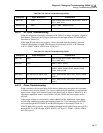
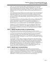
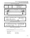
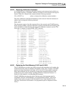
Table 5A-8. Display Initialization (2635A)
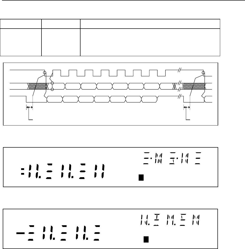
A2TP4 DTEST* A2TP5 LTE* POWER-UP DISPLAY INITIALIZATION
1
1
0
0
1
0
1
0
All Segments OFF
All Segments ON (default)
Display Test Pattern #1
Display Test Pattern #2
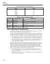
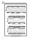
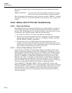
BIT 7
BIT 7
HOLD OFF
CLEAR TO
RECEIVE
31.5 µs
DISTX
DSCLK
DISRX
CLEAR TO
RECEIVE
31.5 µs
BIT 6 BIT 5 BIT 4 BIT 3 BIT 2 BIT 1 BIT 0
BIT 6 BIT 5 BIT 4 BIT 3 BIT 2 BIT 1 BIT 0
s54f.eps
Figure 5A-9. Display Controller to Microprocessor Signals (2635A)
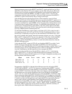
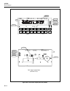
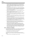
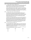
REVIEW
REM SCAN
x1 k
EXT
SET
FUNC
mV
TR
1
Ω
s51f.eps
Figure 5A-10. Display Test Pattern #1 (2635A)
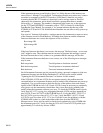
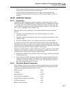
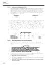
LAST
MAX
MIN AUTO MON
M
LIMIT
HI
LO
OFF
CAL
PRN
Mx+B
ALARM
°C °F RO
AC DC
Hz
CH
2
F
s52f.eps
Figure 5A-11. Display Test Pattern #2 (2635A)
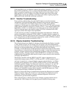
Note
If the display is operational but has problems whenfront-panel buttons are
pressed, proceed directlyto step 9.
1. Check the three power supplies with respect to GND (A2TP3 or A2U1-42) on the
Display Assembly.
VCC (A2U1-21)
VEE (A2U1-4)
VLOAD A2U1-5)
4.75 to 5.25V dc
-4.75 to -5.25V dc
-28.5 to -32.0V dc