


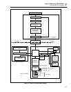

Theory of Operation (2620A/2625A)
Detailed Circuit Description
2
2-13
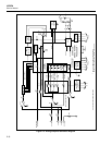
2-39. EEPROM
The EEPROM contains 64 registers, each of which is 16 bits long. These registers are
used to provide nonvolatile storage of some of the instrument configuration information
and all of the calibration information. When the Microprocessor is communicating to the
EEPROM, Chip Select input (A1U1-1) is driven high to enable the EEPROM interface.
When the Microprocessor is reading data from the EEPROM, the data bits are serially
shifted out on the Data Out signal (A1U1-4) with each one-to-zero transition of the
Serial Clock (A1U1-2).
When the Microprocessor is writing commands and data to the EEPROM, the bits are
serially shifted into the EEPROM on the Data In signal (A1U1-3) with each zero-to-one
transition of the Serial Clock (A1U1-2). When the last data bit for an erase or write
operation is shifted into the EEPROM, the Microprocessor pulses the Chip Select input
(A1U1-1) low to start the operation. The EEPROM will then drive the Data Out signal
(A1U1-4) low to indicate that it is busy writing the register. The Data Out signal goes
high when the operation is complete. Since the Microprocessor waits for this signal to go
high before doing anything else, an EEPROM failing to drive this signal high causes the
Microprocessor to wait until the Watchdog Timer on the Display PCA resets the
instrument.
The Chip Select input (A1U1-1) is always set low at the end of each EEPROM
operation.
2-40. Counter/Timer
The Counter/Timer IC (A1U2) has three 16-bit counters that are used both to implement
the Totalizer function and to provide a periodic 50-millisecond interrupt used for interval
time operation.
The output from the Totalizer Input circuit (A1U28-3) provides the clock input for
Counter 2. Counter 2 operates as a 16-bit pre-loadable down counter for the Totalizer
function. This counter causes the IRQ1* interrupt (A1U2-9) to go low, interrupting the
Microprocessor when the counter value changes from hexadecimal 0000 to FFFF. The
Counter 2 Gate input (A1U2-2) must be low for the Totalizer to operate correctly.
Counter 3 is used as a periodic 50.0-millisecond interrupt source. This counter divides
the E clock input (A1U2-17) by 61440. The IRQ1* interrupt (A1U2-9) goes low
(interrupting the Microprocessor) at the end of each 50.0-millisecond period. The
Counter 3 Gate input (A1U2-5) and the Counter 3 Clock input (A1U2-7) should both be
low for this counter to operate correctly. The 10-Hz square wave signal observed on the
Counter 3 Output pin (A1U2-6) changes state every 50.0 milliseconds.
Counter 1 is not used in the instrument, but its Clock and Output pins have been
connected to available pins on the Option Interface.
2-41. RS-232 Interface
The RS-232 interface is composed of connector A1J4, RS-232 Driver/Receiver A1U25,
and the hardware serial communication interface (SCI) in Microprocessor A1U4.
The SCI transmit signal (A1U4-14) goes to the RS-232 driver (A1U25-12), where it is
inverted and level shifted so that the RS-232 transmit signal transitions between
approximately +5.0 and -5.0V dc. When the instrument is not transmitting, the driver
output A1U25-5 is approximately -5.0V dc. The RS-232 receive signal from A1J4 goes
to the RS-232 receiver A1U25-4, which inverts and level shifts the signal so that the
input to the SCI transitions between 0 and +5.0V dc. When nothing is being transmitted
to the instrument, the receiver output (A1U25-13) is +5.0V dc.