


General Maintenance
Assembly Procedures
3
3-13
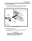
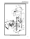
3-20. Disconnect Miscellaneous Chassis Components
Use the following procedure to disconnect the remaining hardware from the chassis.
Parts referenced by letter (e.g., A) are shown in Figure 3-4 (2620A or 2625A) or Figure
3-5 (2635A).
1. Use needle nose pliers to remove the internal connections at the line power plug (X).
Remove the ground screw prior to disconnecting the ground wire from the plug.
2. Remove the power plug by releasing its two snaps one at a time.
3. Disconnect the power transformer by removing the four 5/16-inch nuts (Y) that
secure it to the right side of the chassis.
4. If installed, remove the 7-mm IEEE-488 connector screws (Z) (2620A only).
3-21. Assembly Procedures
Generally, assembly procedures follow a reverse sequence of disassembly procedures.
As some differences do apply, assembly is described separately in the following
paragraphs. Begin assembly at the appropriate level, as defined by the heading.
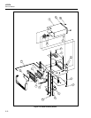
References are made to items in Figure 3-4 (2620A or 2625A) or Figure 3-5 (2635A) for
assembly details of standard instrument parts.
Note
Parts referenced by letter (e.g., A) are shown in Figure 3-4 (2620A or
2625A) or Figure 3-5 (2635A).
3-22. Install Miscellaneous Chassis Components
Use the following procedure to replace any items that have been removed from the basic
chassis.
1. Replace the power transformer along the right side of the chassis. Use four 5/16-inch
hex nuts (Y).
2. Snap the power plug into position.
3. Use needle nose pliers to replace the interior connections at the power plug. Also,
attach the ground wire at its chassis connection.
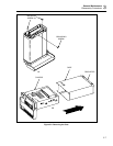
3-23. Install the A/D Converter PCA
1. Fit the A/D Converter PCA (L) so that the chassis guides pass through notches on
both sides of the pca. Then slide the pca back until it is snug against the Input
Module enclosure.
2. Fasten the A/D Converter PCA to the chassis with three 6-32, 1/4-inch panhead
screws (W).
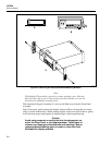
3. If the Front Panel Assembly is installed, attach the leads connecting the two input
terminals to the A/D Converter PCA. Using needle nose pliers, push the wire
connectors firmly onto the recessed input terminal pins (red to VΩ and black to
COM.)
4. At the A/D Converter PCA, attach the cable leading to the Main PCA.
5. From the Rear Panel, push the Input Module back into place.