


Performance Testing and Calibration
Performance Tests
4
4-13
6. The RTD Temperature Accuracy test is complete. However, if you desire to perform
this test on any other channel (0 or 2 through 20), repeat steps 1 through 5,
substituting the appropriate channel number.
Note
The only type of temperature measurement that can be made on channel 0
is 2-terminal RTD. Channels 11 through 20 support only 2-terminal RTDs.
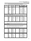
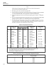
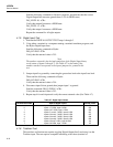
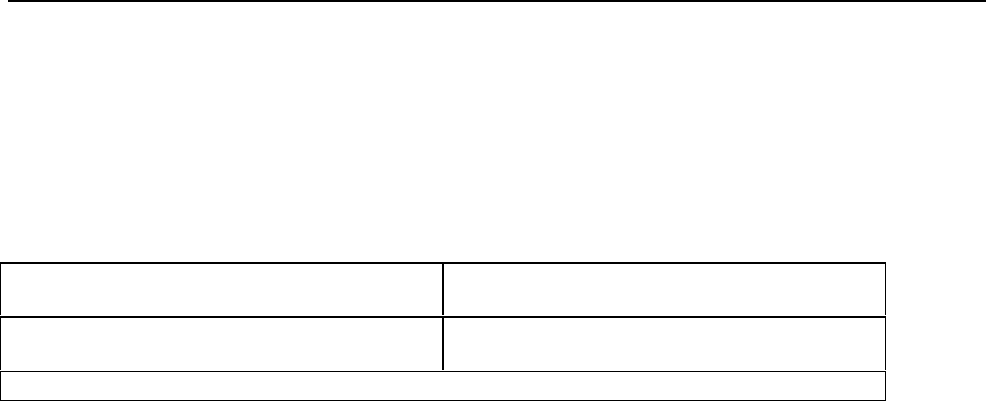
Table 4-6. Performance Tests for RTD Temperature Function (DIN/IEC 751)
RTD Type
(DIN 43760 RTD)
Temperature Accuracy Specifications
1 Year @ 18-28°C
2-wire (channel 0)
4-wire
-0.65°C to +0.70°C
-0.65°C
(Assumes RTD R0 is set to 100.00Ω for each channel.)
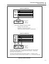
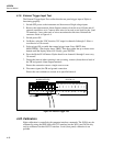
4-13. Digital Input/Output Verification Tests
Digital Input/Output verification testing requires computer interfacing with a host
(terminal or computer). The host must send commands to the instrument to control the
digital lines for this test. Refer to Section 4 of the Hydra Users Manual for a description
of configuring and operating the instrument.
4-14. Digital Output Test.
1. Ensure that communication parameters (i.e., transmission mode, baud rate, parity,
and echo mode) on Hydra and the host are properly configured to send and receive
serial data.
2. Switch OFF power to the instrument and disconnect all high voltage inputs.
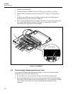
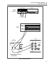
3. Remove the ten-terminal Digital I/O connector from the rear of the instrument and
all external connections to it. Connect short wires (to be used as test leads) to the
ground (G) and 0 through 7 terminals. Leave the other wire ends unconnected at this
time. Reinstall the connector.
4. Switch power ON to both Hydra and the host. Verify that Hydra is not scanning. If
Hydra is scanning, press SCAN to turn scanning off, then cycle power off and on
again.
5. Using a digital multimeter (DMM), verify that all digital outputs (0-7) are in the
OFF or HIGH state. This is done by connecting the low or common of the
multimeter to the ground test lead and the high of the multimeter to the digital output
and verifying a voltage greater than +3.8V dc.
6. Using either a terminal or a computer running a terminal emulation program, set up
Hydra to turn Digital Outputs ON (LOW state).
In sequence send the following commands to Hydra and measure that the correct
Digital Output line measures less than +0.8V dc (LOW state.)
DO_LEVEL 0,0 <CR>
Verify that output 0 measures a LOW state.
DO_LEVEL 1,0 <CR>
Verify that output 1 measures a LOW state.
DO_LEVEL 2,0 <CR>
Verify output 2 measures a LOW state.
Repeat the command for all eight outputs.
7. Set up Hydra to turn Digital Outputs OFF (HIGH state).