


Theory of Operation (2635A)
Detailed Circuit Description
2A
2A-31
BUFFER
A3Z2
INTEGRATOR
INTEGRATE
REFERENCE
INTEGRATE
INPUT
–REFERENCE
(+ INPUT)
REFERENCE
+ REFERENCE
(– INPUT)
S77
A3C13
+
_
_
+
+
_
A/D
COMPARATOR
+
_
COUNTER
INPUT HI
INPUT LO
s17f.eps
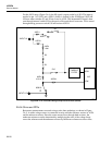
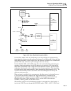
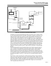
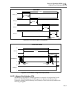
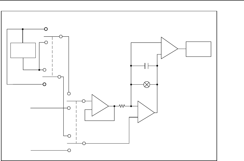
Figure 2A-7. A/D Converter Simplified Schematic (2635A)
In both the slow and fast measurement rates, the a/d converter uses its ±300 mV range
for most measurement functions and ranges. The primary exceptions are that the 3V dc
range is measured on the a/d converter 3V range, thermocouples are measured on the
±100 mV range, and the temperature reference is measured on the 1V a/d converter
range. The typical overload point on a slow rate 30000 count range is 32000 display
counts; the typical overload point on a fast rate 3000 count range is 3200 display counts.
During the integrate phase, the a/d buffer in the A3U8 Analog Measurement Processor
applies the signal to be measured to one of the four integrator input resistors in network
A3Z2. As shown on the A/D Converter schematic diagram in Section 8, the choice of
resistor selects the a/d converter range. Switch S69 connects the buffer output through
pin B.1 for the 100-mV range, S71 connects the output through B.32 for the 300 mV
range, S73 connects to pin B1 for the 1V range, and S75 sets up the 3V range through
pin B3.2.
The current through the selected integrator input resistor charges integrator capacitor
A3C13, with the current dependent on the buffer output voltage. After the integrate
phase, the buffer is connected to the opposite polarity reference voltage, and the
integrator integrates back toward zero capacitor voltage until the comparator trips. An
internal counter measures this variable integrate time. If the a/d converter input voltage
is too high, the integrator overloads and does not return to its starting point by the end of
the measurement phase. Switch S77 is then turned on to discharge integrate capacitor
A3C13.
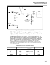
The reference voltage used during the variable integrate period for voltage (and high
ohms) conversions is generated from zener reference diode A3VR1, which is time and
temperature stable. The reference amplifier in the Analog Measurement Processor, along
with resistors A3R15, A3R18, and A3R21, pulls approximately 2 mA of current through
the zener. Resistors in network A3Z2 divide the zener voltage down to the reference
1.05V required by the A/D Converter.