


HYDRA
Service Manual
2-14
Data Terminal Ready (DTR) is a modem control signal controlled by the
Microprocessor. When the instrument is powered up, the Microprocessor port pin
(A1U4-32) goes high, which results in the RS-232 driver output (A1U25-7) going to -
5.0V dc. When the instrument has initialized the SCI and is ready to receive and
transmit, A1U4-32 will go low, resulting in the RS-232 DTR signal (A1U25-7) going to
+5.0V dc. The RS-232 DTR signal remains at +5.0V dc until the instrument is powered
down.
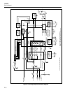
2-42. Option Interface
The interconnection to the option slot is implemented by J1 on the Main PCA. This
connector (A1J1) routes the outguard logic power supply (VCC and GND), the eight-bit
data bus, RD*, WR*, E, RESET*, IEEE*, MEM*, and the lower three bits of the address
bus to the option installed in the option slot. This connector also routes an interrupt
signal from the IEEE-488 option to the IRQ2* input of the Microprocessor.
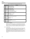
An option sense signal from the installed option allows the Microprocessor to identify
the type of option. When the instrument is powered up, the type of PCA installed in the
option slot is determined by the Microprocessor by driving the IRQ2* signal (A1U4-20)
and sensing the activity on the OPS* signal (A1U4-29). The Microprocessor first sets
IRQ2* low and samples the OPS* input, then sets IRQ2* high and samples the OPS*
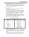
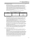
input again. Table 2-2 describes how this information is used to determine what
hardware is installed in the option slot.
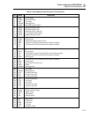
Table 2-2. Option Type Sensing
IRQ2* Output
State of *OPS Input for PCA:
None Installed IEEE-488 Memory
0100
1101
2-43. Digital I/O
The following paragraphs describe the Digital Input Threshold, Digital Input Buffers,
Digital and Alarm Output Drivers, Totalizer Input, and External Trigger Input circuits.