


HYDRA
Service Manual
5-12
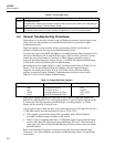
5-10. Analog Troubleshooting
Warning
To avoid electric shock, disconnect all channelinputs from the
instrument before performing anytroubleshooting operations.
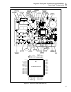
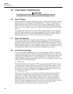
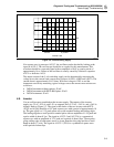
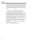
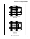
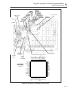
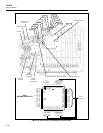
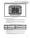
Refer to Figure 5-4 and Figure 5-5 for test point locations on the A/D Converter PCA.
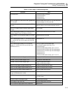
First, check for analog-related errors displayed at power up. An ’Error 9’ means that the
Main Microprocessor A1U4 is not able to communicate with the A/D Microcontroller
A3U9. ’Error A’ and ’Error b’ mean that a failure has occurred in the internal memory of
the A/D Microcontroller A3U9. ’Error C’ means that the Analog Measurement Processor
A3U8 is not functioning properly.
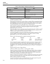
Check the inguard power supplies on the Main PCA with and without the A/D Converter
PCA connected. The inguard supplies must be measured with respect to COM testpoint
A1TP30.
Power Supply Test Location Acceptable Range
VDD
VSS
VDDR
A1TP31
A1TP32
A1C6
+5.00 to 5.70V dc
-5.10 to -5.75V dc
5.30 to 5.95V dc
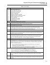
Check the inguard supply voltages on the A/D Converter PCA with respect to A3TP9.
The following table lists the components nearest the power supply test points.
Power Supply Test Location Acceptable Range
VDD
VSS
VDDR
+VAC
-VAC
A3C8
A3C9
A3C19
A3CR1
A3C26
5.00 to 5.70V dc
-5.10 to -5.75V dc
5.30 to 5.95V dc
4.7 to 5.7V dc
-4.8 to -5.7V dc