


HYDRA
Service Manual
5-14
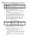
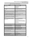
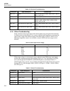
Table 5-3. Power Supply Troubleshooting Guide (cont)
Symptom Fault
A1U18 hot. Shorted A1C32
A1U18 oscillates. Open A1C32.
A1U19 oscillates. Open A1C34.
A1U19 very hot. - Shorted A1U22 (VCC to VSS).
- Shorted A1U23 (VCC to VSS).
A1U19 hot. Shorted A1C34.
Check that the inguard Microcontroller A3U9 RESET* line is de-asserted. Check VDD
at A3TP1, referenced to A3TP9.
Check that the microcontroller crystal oscillator is running. When measured with a high
input impedance oscilloscope or timer/counter, the oscillator output at A3TP10 should
be a 3.6864-MHz sine wave (271.3 ns period), and the divided-down E clock output at
A3U9 pin 68 should be a 921.6 kHz-square wave (1.085 µs period).
Check outguard to inguard communication. Setup an input channel and enable monitor
measurements on that channel, causing the outguard to transmit to the inguard
approximately every 10 seconds.
On the Main PCA, look for outguard-to-inguard communication (5.1V (VCC) to near 0V
pulses) at A1TP15, referenced to A1TP1. On the A/D Converter PCA, check for 5.35V
(VDD) to near 0V pulses at A3TP8, referenced to A3TP9.
At the start of outguard-to-inguard communication, the A/D Microcontroller (A3U9)
should be RESET. Check for this reset pulse (5.35V (VDD) to near 0V, lasting
approximately 1-ms) on A3TP1 with respect to A3TP9.
Check for the following inguard-to-outguard communication activity:
PCA Test Point To Pulses
A/D Converter
Main
A3TP7
A1TP8
A3TP9
A1TP1
5.55V (VDDR) to 0.7V
0V dc to 5.1V (VCC)
Lack of outguard-to-inguard communication activity may be due to improper operation
of circuit elements other than A3U9. Using a high input impedance oscilloscope or
timer/counter, check for proper Analog Processor (A3U8) crystal oscillator operation. A
3.84-MHz sine wave (260 ns period) should be present at A3U8 pin 37 with respect to
A3TP9.
Check the A/D Converter voltage reference:
A3TP12 to A3TP11 (across A3C12) = +1.05V (+0.10V, -0.02V)
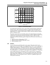
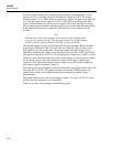
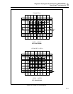
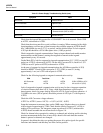
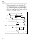
Setup the instrument to measure ohms on the 300Ω range. Monitor ohms on a channel
with an input of approximately 270Ω. Check that the Analog Processor IC (A3U8) is
making A/D conversions. The integrator output waveform at A3TP13 (referenced to
A3TP9) should resemble the waveform shown in Figure 5-6.
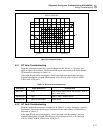
Check for channel relay operation by setting up a channel and selecting and de-selecting
monitor measurement mode. One or more relays should click each time the monitor
button is pressed or channels are changed.
In general, check that the relays are getting the proper drive pulse signals for specific
functions and channels and that they are in the correct position.