


HYDRA
Service Manual
4-6
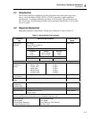
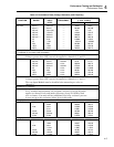
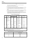
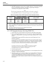
Table 4-2. Performance Tests (Voltage, Resistance, and Frequency) (cont)
FUNCTION RANGE INPUT FREQUENCY
DISPLAY ACCURACY
(1 Year, 18-28°C)
LEVEL MIN MAX
300Ω
3 kΩ
3 kΩ
30 kΩ
300 kΩ
3 MΩ
10 MΩ
short
100Ω
short
1 kΩ
10 kΩ
100 kΩ
1 MΩ
10
0.00
99.92
0.0000
0.9992
9.992
99.92
0.9992
9.986
0.09
100.15
0.0003
1.0009
10.008
100.08
1.0008
10.014
* Optional test point if standards available.
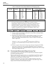
Note
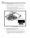
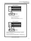
All channels (0 through 20) can accommodate 2-terminal resistance
measurements. Channel 0, with only two connections, cannot be used for 4-
terminal measurements. Four-terminal resistance measurements can be
defined for channels 1 through 10 only. Channels 11 through 20 are used,
as required, for 4-terminal to provide the additional two connections. For
example, a 4-terminal set up on channel 1 uses channels 1 and 11, each
channel providing two connections.
Frequency 90 kHz 10 kHz/2V p-p 9.994 10.006
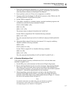
8. Connect a cable from the Output VA HI and LO of the 5700A to the Input Module
test leads (observe proper polarity).
9. Select the VDC function and 300-volt range on Hydra and apply 0V dc from the
5700A. Then apply 290V dc input from the 5700A. Ensure the display reads
between the minimum and maximum values as shown in Table 4-2 for the 0 and
290V dc input levels.
Note
Channels 0, 1, and 11 can accommodate a maximum input of 300V dc or
ac. However, the maximum input for all other channels can only be 150V
dc or ac.
10. With the exception of the selected voltage range and input voltagefrom the 5700A,
repeat steps 1 through 9 for each remaining InputModule channel (2 through 20).
Channels 2 through 10 and 12 through20 should be configured for the 150V dc range
and an input voltageof 150 volts.
4-6. Thermocouple Measurement Range Accuracy Test
Verify that the Accuracy Verification Test for channel 0 meets minimum acceptable
levels before performing this test.
Thermocouple temperature measurements are accomplished using the Hydra internal
100 mV and 1V dc ranges. (The ranges are not configurable by the operator.) This
procedure provides the means to test these ranges.
Testing the 100 mV and 1V dc ranges requires computer interfacing with a host
(terminal or computer). The host must send commands to select these ranges. These
ranges cannot be selected from the Hydra front panel.