


Diagnostic Testing and Troubleshooting (2635A)
Power Supply Troubleshooting
5A
5A-9
5A-9. Inverter
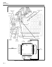
Use an oscilloscope to troubleshoot the inverter supply. The outputs of the inverter
supply are -5V dc (VEE), -30V dc (VLOAD), and 5.4V ac (FIL1 and FIL2) outguard,
and +5.3V dc (VDD), -5.4V dc (VSS), and +5.6V dc (VDDR) inguard. Refer to Figure
5A-3. The signal at the drains of the two inverter switch FETs (A1Q7 and A1Q8) should
be a 10V peak square wave with a period of approximately 18 us. The gate signal is a
5.1V peak square wave with rounded leading and trailing edges. The leading edge has a
small positive rounded pulse with an amplitude of 1.8V peak and a pulse width of about
0.3 us. The signal at A1U22-5 and A1U22-6 is a symmetrical square wave with an
amplitude of 5.1V peak and a period of about 18 us. The negative-going trailing edge of
both square waves is slower than the rising edge and has a small bump at about 1.5 volts.
The signal at A1U22-3 (TP14) is a symmetrical square wave with a period of about 9 us.
For the inverter to operate, the 110-kHz oscillator must be operating properly. If the
signal at A1U22-3 is missing, begin by checking the voltage at A1TP7. The voltage
should be about +5.3V dc. Then, using an oscilloscope, check for a square wave signal at
A1U23-9 and a square wave signal at A1U23-8. If the FETs are getting proper drive
signals, failures that heavily load the inverter supply will usually cause the inverter to
draw enough current to make the switcher supply go into current limit. Shorted rectifier
diodes and shorted electrolytic capacitors will cause heavy load conditions for the
inverter.
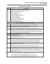
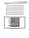
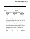
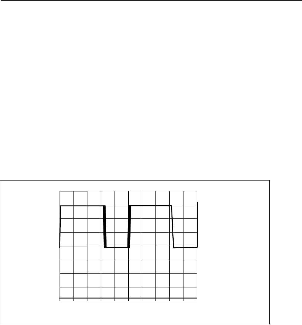
U9-7 and T2-2
5V/DIV
0V
20V
2 µS/DIV
Normal Load
s33f.eps
Figure 5A-2. 5-Volt Switching Supply (2635A)