


3-1
Chapter 3
General Maintenance
Title Page
3-1. Introduction .......................................................................................... 3-3
3-2. Warranty Repairs and Shipping ........................................................... 3-3
3-3. General Maintenance............................................................................ 3-3
3-4. Required Equipment ........................................................................ 3-3
3-5. Power Requirements ........................................................................ 3-3
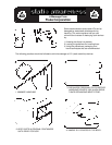
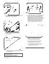
3-6. Static Safe Handling ........................................................................ 3-3
3-7. Servicing Surface-Mount Assemblies.............................................. 3-4
3-8. Cleaning................................................................................................ 3-4
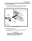
3-9. Line Fuse Replacement ........................................................................ 3-5
3-10. Disassembly Procedures....................................................................... 3-5
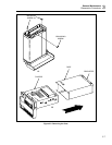
3-11. Remove the Instrument Case ........................................................... 3-6
3-12. Remove Handle and Mounting Brackets ......................................... 3-6
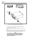
3-13. Remove the Front Panel Assembly.................................................. 3-6
3-14. Remove the Display PCA ................................................................ 3-6
3-15. Remove the IEEE-488 Option (2620A Only).................................. 3-11
3-16. Remove the Memory PCA (2625A Only)........................................ 3-11
3-17. Remove the Memory Card I/F PCA (2635A Only) ......................... 3-11
3-18. Remove the Main PCA .................................................................... 3-12
3-19. Remove the A/D Converter PCA..................................................... 3-12
3-20. Disconnect Miscellaneous Chassis Components............................. 3-13
3-21. Assembly Procedures ........................................................................... 3-13
3-22. Install Miscellaneous Chassis Components..................................... 3-13
3-23. Install the A/D Converter PCA........................................................ 3-13
3-24. Install the Main PCA........................................................................ 3-14
3-25. Install the IEEE-488 Option (2620A Only) ..................................... 3-14
3-26. Install the Memory PCA (2625A Only)........................................... 3-14
3-27. Install the Memory Card I/F PCA (2635A Only) ............................ 3-15
3-28. Assemble the Front Panel Assembly ............................................... 3-15
3-29. Install the Front Panel Assembly..................................................... 3-15