


HYDRA
Service Manual
2-28
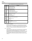
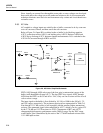
The coils for the relays are driven by the outputs of Darlington drivers A3U4, A3U5,
A3U10, A3U11, and A3U12. The relays are switched when a 6-millisecond pulse is
applied to the appropriate reset or set coil by the NPN Darlington drivers in these ICs.
When the port pin of Microcontroller A3U9 connected to the input of a driver is set high,
the output of the driver pulls one end of a relay set or reset coil low. Since the other end
of the relay coil is connected to the VDDR supply, a magnetic field is generated, causing
the relay armature and contacts to move to (or remain in) the desired position.
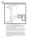
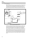
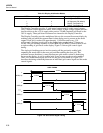
2-62. Open Thermocouple Check
Immediately before a thermocouple measurement, the open thermocouple check circuit
applies a small, ac-coupled signal to the thermocouple input. Microcontroller A3U9
initiates the test by asserting OTCEN, causing comparator A3U14/A3R40 to turn on
JFET A3Q12. Next, the Microcontroller sends a 78-kHz square wave out the OTCCLK
line through A3R41, A3Q12, and A3C32 to the thermocouple input. The resulting
waveform is detected by A3U13 and A3CR2, and a proportional level is stored on
capacitor A3C30. Op amp A3U13 compares this detected level with the VTH threshold
voltage set up by A3R37 and A3R36 and stored on A3C29. If the resistance at the input
is too large, the VTH level will be exceeded and the OTC (open thermocouple check)
line will be asserted. After a short delay, the Microcontroller analyzes this OTC signal,
determines whether the thermocouple should be reported as open, and deasserts OTCEN
and sets OTCCLK high, ending the test.
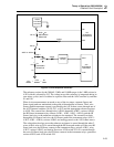
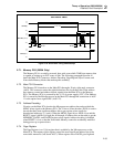
2-63. Input Connector PCA
The Input Connector assembly, which plugs into the A/D Converter PCA from the rear
of the instrument, provides 20 pairs of channel terminals for connecting measurement
sensors. This assembly also provides the reference junction temperature sensor circuitry
used when making thermocouple measurements.
Circuit connections between the Input Connector and A/D Converter PCAs are made via
connectors A4P1 and A4P2. Input channel and earth ground connections are made via
A4P1, while temperature sensor connections are made through A4P2.
Input connections to channels 1 through 20 are made through terminal blocks TB1 and
TB2. Channel 1 and 11 HI and LO terminals incorporate larger creepage and clearance
distances and each have a metal oxide varistor (MOV) to earth ground in order to clamp
voltage transients. MOVs A4RV1 through A4RV4 limit transient impulses to the more
reasonable level of approximately 1800V peak instead of the 2500V peak that can be
expected on 240 VAC, IEC 664 Installation Category II, ac mains. In this way, higher
voltage ratings can be applied to channels 1 and 11 than can be applied to the other rear
channels.
Strain relief for the user’s sensor wiring is provided both by the Connector PCA housing
and the two round pin headers. Each pin of the strain relief headers is electrically
isolated from all other pins and circuitry.
Temperature sensor transistor A4Q1 outputs a voltage inversely proportional to the
temperature of the input channel terminals. This voltage is 0.6V dc at 25ºC, increasing 2
mV with each degree decrease in temperature, or decreasing 2 mV with each degree
increase in temperature. For high accuracy, A4Q1 is physically centered within and
thermally linked to the 20 input terminals. Local voltage reference A4VR1 and resistors
A4R1 through A4R3 set the calibrated operating current of the temperature sensor.
Capacitor A4C1 shunts noise and EMI to ground.