


HYDRA
Service Manual
2A-36
Once reset, the Display Controller performs a series of self-tests, initializing display
memory and holding the DISRX signal high. After DISRX goes low, the Display
Controller is ready for communication. On the first command byte from the
Microprocessor, the Display Controller responds with a self-test results response. If all
self-tests pass, a response of 00000001 (binary) is returned. If any self-test fails, a
response of 01010101 (binary) is returned. The Display Controller initializes its display
memory to one of four display patterns depending on the states of the DTEST* (A2U1-
41) and LTE* (A2U1-13) inputs. The DTEST* input is pulled up by A2Z1, but may be
pulled down by jumpering A2TP4 to A2TP3 (GND). The LTE* input is pulled down by
A2R12, but may be pulled up by jumpering A2TP5 to A2TP6 (VCC). The default
conditions of DTEST* and LTE* cause the Display Controller to turn all segments on
bright at power-up.
Table 2A-8 defines the logic and the selection process for the four display initialization
modes.
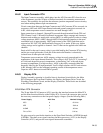
Table 2A-8. Display Initialization Modes (2635A)
A2TP4 A2TP5 Power-Up Display Initialization
1 1 All Segments OFF
1 0 All Segments ON (default)
0 1 Display Test Pattern #1
0 0 Display Test Pattern #2
The two display test patterns are a mixture of on and off segments forming a
recognizable pattern that allows for simple testing of display operation. Test patterns #1
and #2 are shown in Section 5 of this manual.
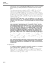
The Display Controller provides 11 grid control outputs and 15 anode control outputs.
(Only 14 anode control outputs are used.) Each of these 26 high-voltage outputs provides
an active driver to the +5V dc supply and a passive 220-kΩ (nominal) pull-down to the -
30V dc supply. These pull-down resistances are internal to the Display Controller.
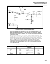
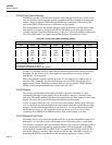
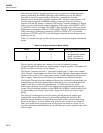
The Display Controller provides multiplexed drive to the vacuum-fluorescent display by
strobing each grid while the segment data for that display area is present on the anode
outputs. Each grid is strobed for approximately 1.37 milliseconds every 16.56
milliseconds, resulting in each grid on the display being strobed about 60.4 times per
second. The grid strobing sequence is from GRID(10) to GRID(0), which results in left-
to-right strobing of grid areas on the display. Figure 2A-9 shows grid control signal
timing.
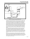
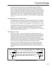
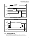
The single grid strobing process involves turning off the previously enabled grid,
outputting the anode data for the next grid, and then enabling the next grid. This
procedure ensures that there is some time between grid strobes so that no shadowing
occurs on the display. A grid is enabled only if one or more anodes are also enabled.
Thus, if all anodes under a grid are to be off, the grid is not turned on. Figure 2A-10
describes the timing relationship between an individual grid control signal and the anode
control signals.