


HYDRA
Service Manual
5A-4
• Surface-mount assemblies require rework with wire solder rather thanwith solder
paste. A 0.025-inch diameter wire solder composed of 63%tin and 37% lead is
recommended. A 60/40 solder is also acceptable.
• A good connection with SMT requires only enough solder to make apositive metallic
contact. Too much solder causes bridging, while toolittle solder can cause weak or
open solder joints. With SMT, theanchoring effect of the through-holes is missing;
solder provides theonly means of mechanical fastening. Therefore, the pca must
beespecially clean to ensure a strong connection. An oxidized pca padcauses the
solder to wick up the component lead, leaving littlesolder on the pad itself.
Refer to the Fluke "Surface Mount Device Soldering Kit" for a complete discussion of
these techniques.
5A-3. Error Codes
At reset, the Hydra Data Bucket software performs power-up self-tests and initialization
of Flash Memory, NVRAM, Display, Calibration Data, and measurement hardware.
Self-test failures are reported on the display with "Error" in the left display and an error
code (1-9,A,b,C,d) in the right display.
Several of these error codes might never be displayed. Certainly, errors 4 and 5, which
signify a faulty or dead display, could not be reported in the normal (displayed) manner.
Other errors might not appear on the display. Therefore, the following additional
methods exist for accessing error information:
• If ’boot’ is displayed at power-up, it is likely that one ofthe memory tests failed
(Errors 1 through 3). To determinewhat the error status was, connect a terminal or
computer to theRS-232 interface (19200 baud, 8 data bits, no parity). Send a
carriagereturn or line feed character to the instrument and it should sendback a
prompt that shows a number followed by a ’>’ character. Thenumber is interpreted in
the same way as the responses for the *TST?and POWERUP? commands; refer to
*TST? in Section 4 of the HydraUsers Manual. For example, a ’4>’ prompt indicates
that the test ofthe NVRAM (A1U20 and A1U24) failed and the instrument was not
ableto safely power-up and operate.
• The computer interfaces can be used to determine self-check statususing the *TST?
query. Refer to Section 4 of the Hydra Data BucketUsers Manual for a description of
the *TST? response. Note that theextent of the error-producing damage could also
cause the instrumentto halt before the computer interfaces are operational.
• The POWERUP? computer interface command can be used to determinewhich
errors were detected at power-up. POWERUP? uses the sameresponse format as
*TST?; refer to *TST? in Section 4 of the HydraData Bucket Users Manual.
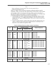
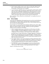
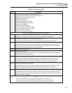
Table 5A-1 describes the error codes.
Note
Each error code is displayed for 2 seconds.