


HYDRA
Service Manual
5A-20
If the instrument powers up and displays ’boot,’ it is likely that one of the memory test
errors (Errors 1 through 3) was detected. To determine what the error status was, connect
a terminal or computer to the RS-232 interface (19200 baud, 8 data bits, no parity).
Assuming that the RS-232 interface is functional, send a carriage return or line feed
character to the instrument, and it should send back a prompt that shows a number
followed by a ’>’ character. The number is interpreted in the same way as the responses
for the *TST?and POWERUP? commands; refer to *TST? in Section 4 of the Hydra
Data Bucket Users Manual. For example, a ’4>’ prompt indicates that the test of the
NVRAM (A1U20 and A1U24) failed and the instrument was not able to safely power-up
and operate.
Now send a ’t’ character followed by a carriage return to the instrument to request a retest
of the firmware stored in Flash Memory. If both the boot firmware and the instrument
firmware checksums are correct, the response will be as follows:
Boot image OK
Hydra image OK
0>
If the boot firmware checksum is not correct, the message "Bad boot image -- use at own
risk!" might be seen. The code that must be executed to generate this message is part of
the boot firmware that is bad, so there is no guarantee that this message will be seen.
If the instrument firmware checksum is not correct, one of the following error messages
may be seen:
Bad rom pointer "Invalid pointer to checksum structure"
Bad checksum pointer "Invalid pointer to instrument checksum"
Bad checksum "Incorrect instrument checksum"
Invalid instrument firmware may be corrected by using a personal computer to load new
instrument firmware into the Hydra Databucket. To do this see the section entitled
"Updating the 2635A Instrument Firmware" in Section 4 of this manual.
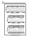
If the NVRAM (A1U20 and A1U24) do not operate correctly, the problem must be
corrected before new instrument firmware may be loaded or the instrument can power up
completely. Use an oscilloscope to check the activity of the address, data, and control
signals to the NVRAM devices (A1U14 and A1U16). It may be necessary to continually
reset (power on) the instrument to check these lines, since the activity probably halts
quickly when the instrument software goes awry. To check the NVRAM control signals,
verify that A1U1-127 is going low, propogating through A1U26, and also appearing on
pins A1U20-22 and A1U24-22 of the NVRAM devices. Verify that RDU* (A1U11-14
and A1U24-24) goes low when A1U1-127 is low. Verify that RDL* (A1U11-19 and
A1U20-24) goes low when A1U1-127 is low. If all this is true, the problem is with the
NVRAM itself or there is a fault in the address/data lines from the MC68302
Microprocessor. It may also be useful to check signal continuity by using a DMM with
the instrument power off. Verify also that pin 30 on A1U24 and A1U20 is pulled up to
approximately 5.0 volts dc by resistor A1R45.