


General Maintenance
Disassembly Procedures
3
3-11
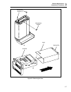
3-15. Remove the IEEE-488 Option (2620A Only)
Section 7 of this manual provides a detailed removal procedure for the IEEE-488 option.
The following removal instructions provide the essentials of this procedure. Parts
referenced by letter (e.g., A) are shown in Figure 3-4. If necessary, refer to the complete
procedure in Section 7.
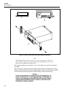
1. From the bottom of the instrument, locate the IEEE-488 PCA (N). This pca is
connected to the front of Main PCA, with a ribbon cable (O) leading across both
pca’s to the Rear Panel.
2. Use needle nose pliers to disconnect the 24-line cable assembly at the IEEE-488
PCA, alternately pulling on each end of the cable connector. Leave the other end of
this cable attached to its Rear Panel connector.
3. Remove the 6-32, 1/4-inch panhead Phillips screw (P) securing the IEEE-488 PCA.
4. Disengage the IEEE-488 PCA by sliding it away from the Main PCA.
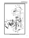
3-16. Remove the Memory PCA (2625A Only)
Use the following procedure to remove the Memory PCA from the 2625A Data Logger.
Parts referenced by letter (e.g., A) are shown in Figure 3-4.
1. From the bottom of the instrument, locate the Memory PCA (Q). This pca is
connected to front of the Main PCA.
Note
You might want to verify that this is the Memory PCA. The Memory PCA
and the IEEE-488 PCA occupy the same position and use the same
connection to the Main PCA. The Memory PCA is a standard part of the
Hydra Data Logger (Model 2625A). The IEEE-488 PCA is not available
with the 2625A but is optional with the Hydra Data Acquisition Unit
(Model 2620A).
2. Remove the panhead Phillips screw (P) securing the Memory PCA.
3. Disengage the Memory PCA by sliding it away from the Main PCA.
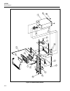
3-17. Remove the Memory Card I/F PCA (2635A Only)
Use the following procedure to remove the Memory Card I/F PCA from the 2635A Data
Bucket. Parts referenced by letter (e.g., A) are shown in Figure 3-5.
1. From the bottom of the instrument, locate the Memory Card I/F PCA (Q). This pca
is in the front of the instrument near the center, and is connected to the Main PCA by
a high-density ribbon cable (O).
2. Remove the three 6-32, 1/4-inch panhead Phillips screws (P) securing the Memory
Card I/F PCA.
3. Disconnect the high-density ribbon cable (O) from the connector on the Memory
Card I/F PCA (Q) and remove the assembly from the chassis.