


HYDRA
Service Manual
4-4
4-3. Performance Tests
When received, the instrument is calibrated and in operating condition. The following
performance verification procedures are provided for acceptance testing upon initial
receipt or to verify correct operation at any time. All tests may be performed in sequence
to verify overall operation, or the tests may be run independently.
If the instrument fails any of these performance tests, calibration adjustment and/or
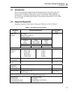
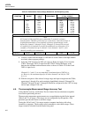
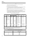
repair is needed. To perform these tests, use a Fluke 5700A Multifunction Calibrator or
equipment that meets the minimum specifications given in Table 4-1.
Each of the measurements listed in the following steps assumes the instrument is being
tested after a 1/2 hour warmup, in an environment with an ambient temperature of 18 to
28 degrees Celsius and with a relative humidity of less than 70%.
Note
All measurements listed in the performance test tables are made in the slow
reading rate unless otherwise noted.
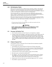
Warning
Hydra contains high voltages that can be dangerous or fatal.
Only qualified personnel should attempt to service the
instrument.
4-4. Accuracy Verification Test
1. Power up the instrument and wait 1/2 hour for its temperature to stabilize.
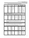
2. Connect a cable from the Output VA HI and LO connectors of the 5700A to the VΩ
and COM connectors on the Hydra front panel. Select the channel 0 function and
range on Hydra and the input level from the 5700A using the values listed in Table
4-2. Press MON to measure and display the measurement value for channel 0. The
display should read between the minimum and maximum values (inclusive) listed in
the table.
4-5. Channel Integrity Test
Verify that the Accuracy Verification Test for channel 0 meets minimum acceptable
levels before performing this test.
1. Switch OFF power to the instrument and disconnect all high voltage inputs.
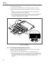
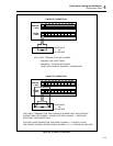
2. Remove the Input Module from the rear of the instrument. Open the Input Module
and connect a pair of test leads to the H (high) and L (low) terminals of channel 1.
Reinstall the Input Module into the instrument.
3. Connect the ends of the test leads together to apply a short (0 ohms).
4. Reconnect power, and turn the instrument ON.
5. For channel 1, select the 2-terminal ohms function and 300-ohms range on Hydra.
Press MON and ensure that the display reads a resistance of less than or equal to
4.0Ω. (This test assumes that lead wire resistances are less than 0.1Ω.)
6. Open the ends of the test leads and ensure that the display reads "OL" (overload).
7. Press MON to stop the measurement.