


HYDRA
Service Manual
5-4
• A good connection with SMT requires only enough solder to make apositive metallic
contact. Too much solder causes bridging, while toolittle solder can cause weak or
open solder joints. With SMT, theanchoring effect of the through-holes is missing;
solder provides theonly means of mechanical fastening. Therefore, the pca must
beespecially clean to ensure a strong connection. An oxidized pca padcauses the
solder to wick up the component lead, leaving littlesolder on the pad itself.
Refer to the Fluke "Surface Mount Device Soldering Kit" for a complete discussion of
these techniques.
5-3. Error Codes
At reset, the Hydra software performs power-up self-tests and initialization of ROM,
NVRAM, Display, EEPROM, and measurement hardware. Self-test failures are reported
on the display with "Error" in the left display and an error code (1-9,A,b,C) in the right
display.
Several of these error codes might never be displayed. Certainly, errors 4 and 5, which
signify a faulty or dead display, could not be reported in the normal (displayed) manner.
Other errors might not appear on the display. Therefore, the following additional
methods exist for accessing error information:
• The computer interfaces can be used to determine self-check statususing the *TST?
query. Refer to Section 4 of the Hydra Users Manualfor a description of the *TST?
response. Note that the extent of theerror-producing damage could also cause the
instrument to halt beforethe computer interfaces are operational.
• The POWERUP? computer interface command can be used to determinewhich
errors were detected at power-up. POWERUP? uses the sameresponse format as
*TST?; refer to *TST? in Section 4 of the HydraUsers Manual.
• The keyboard scan lines (A1U4, SWR1-5), which are also used as statusindicators,
can be checked as a last resort for accessing errorinformation. The software sets
SWR1 (A1U4-21) low to indicate thatthe basic operation of the processor, ROM,
and ROM decode circuitryis intact. SWR2 (A1U4-22) is set low if the ROM (A1U8)
check passes.SWR3 (A1U4-23) is set low if the external NVRAM (A1U3) check
passes,and SWR4 (A1U4-24) is set low if the internal RAM (A1U4) checkpasses.
Then, if the display self-check passes, SWR5 (A1U4-25) isset low to indicate that
the display is operational.
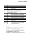
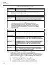
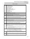
Table 5-1 describes the error codes.
Note
Each error code is displayed for 2 seconds.