


Performance Testing and Calibration
Calibration
4
4-23
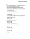
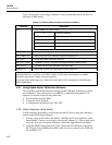
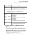
Once the calibrator output has been set to Hydra, the CAL_STEP? query performs the
calibration step and returns the calibrated value of the input. The response to
CAL_STEP? must be received before each new step can begin. With some steps, a
noticeable delay may be encountered.
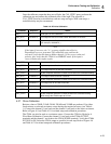
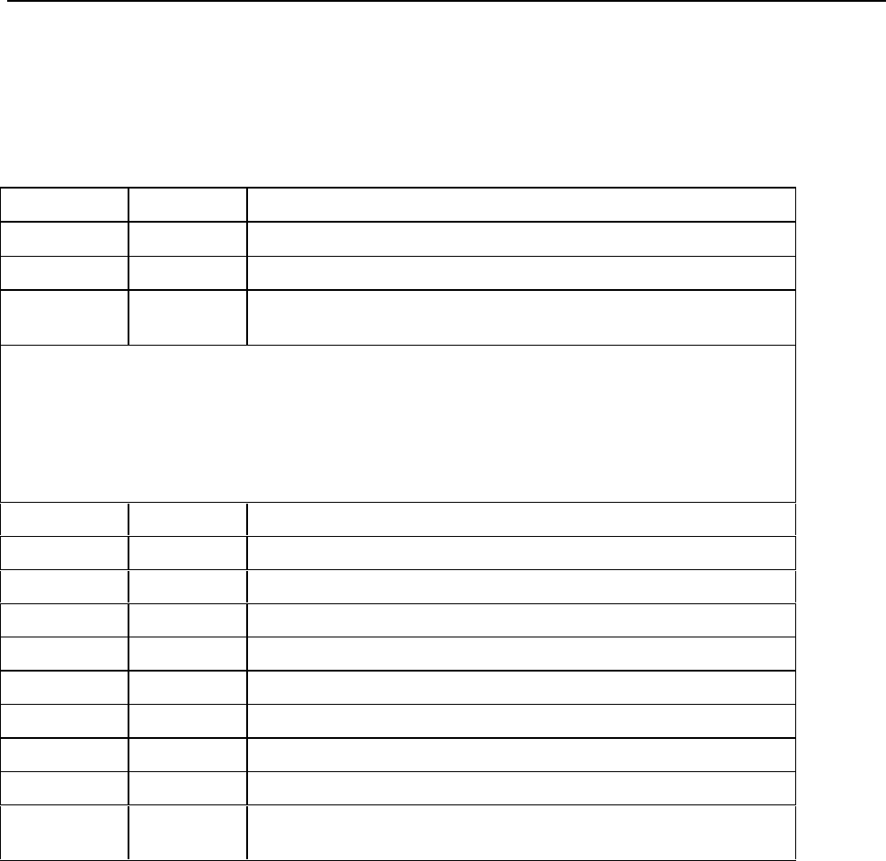
Table 4-9. DC Volts Calibration
Command Response Action
CAL 1 => Puts Hydra in VDC Calibration.
CAL_REF? +90.000E-3 You output 90 mV dc from the 5700A. Wait about 10 seconds.
CAL_STEP? Hydra computes calibration constant 1 and returns the calibrated reading
(for example, +90.000E-3.)
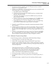
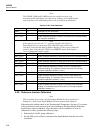
Note
If the input is incorrect, the "!>" response signifies that a Device
Dependent Error was generated. The calibration step could not be
executed. Verify that the input to Hydra channel 1 is the correct value and
polarity. Also verify that the 5700A is in OPERATE mode. If the input is
correct, Hydra may require repair.
CAL_REF? +900.00E-3 You output 900 mV dc from the 5700A. Wait 4 seconds.
CAL_STEP? Hydra computes calibration constant 2 and returns the calibrated reading.
CAL_REF? +290.00E-3 You output 290 mV dc and wait 4 seconds.
CAL_STEP? Hydra computes calibration constant 3 and returns the calibrated reading.
CAL_REF? +2.9000E+0 You output 2.9V dc and wait 4 seconds.
CAL_STEP? Hydra computes calibration constant 4 and returns the calibrated reading.
CAL_REF? +29.000E+0 You output 29V dc and wait 4 seconds.
CAL_STEP? Hydra computes calibration constant 5 and returns the calibrated reading.
CAL_REF? +290.00E+0 You output 290V dc and wait 4 seconds.
CAL_STEP? Hydra computes calibration constant 6 returns the calibrated reading.
Now change the 5700A output to 0.0V dc
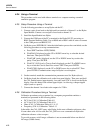
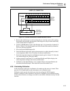
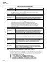
4-27. Ohms Calibration
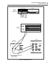
Resistor values of 290Ω, 2.9 kΩ, 29 kΩ, 290 kΩ, and 2.9 MΩ are preferred. Use either
fixed resistors or a decade resistance source having the required accuracy (see Table 4-
1.) Connect the channel 11 test leads and the channel 1 test leads to the source resistance.
Refer to Figure 4-5 and Table 4-11 for related setup and calibration procedures.
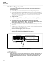
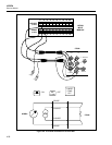
The 5700A can also be used as a resistance source. Connect the 5700A to Hydra for 4-
Wire Ohms Calibration. Connect the channel 11 test leads to the 5700A OUTPUT
terminals and the channel 1 test leads to the 5700A SENSE terminals. Verify that 5700A
EXT SNS is ON. Select the 5700A output as specified in each step. Refer to Figure 4-6
and Table 4-12 for related setup and calibration procedures.