


Theory of Operation (2620A/2625A)
Detailed Circuit Description
2
2-21
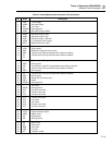
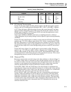
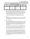
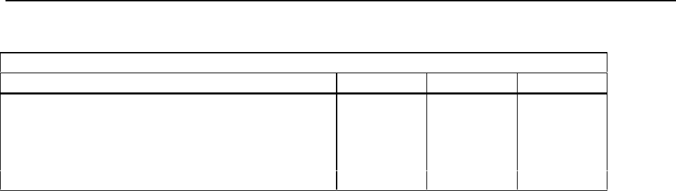
Table 2-5. Function Relay States
Relay Position
Function A3K17 A3K16 A3K15
DC mV, 3V,Thermocouples Reset Set Set
DC 30V, 300V Set Set Set
ACV Set Set Reset
Ohms, RTDs Reset Reset Set
Frequency Set Set Reset
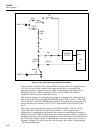
2-54. DC Volts and Thermocouples
For the 3V and lower ranges (including thermocouples), the HI input signal is applied
directly to the A3U8 analog processor through A3R11, A3K17, and A3R42. Capacitor
A3C27 filters this input, which the analog processor then routes through S2 and other
internal switches, through the passive filter, and to the internal a/d converter. The LO
SENSE signal is applied to A3U8 through A3R35 and routed through internal switch
A3U8-S19 to LO of the a/d converter.
Guard signals MGRD and RGRD are driven by an amplifier internal to A3U8 to a
voltage appropriate for preventing leakage from the input HI signal under high humidity
conditions.
For the 30V range, the HI signal is scaled by resistor network A3Z4. Here, the input is
applied to pin 1 of A3Z4 so that an approximate 100:1 divider is formed by the 10-MΩ
and 100.5-kΩ resistors in A3Z4 when analog processor switches S3 and S13 are closed.
The attenuated HI input is then sent through internal switch S12 to the passive filter and
the a/d converter. Input LO is sensed through analog processor switch S18 and resistor
A3R34.
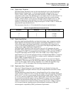
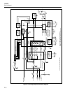
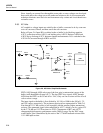
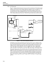
For the 300V range (Figure 2-4), the HI signal is again scaled by A3Z4. The input is
applied to pin 1 of A3Z4, and a 1000:1 divider is formed by the 10-MΩ and 10.01-kΩ
resistors when switches S3 and S9 are closed in A3Z4. The attenuated HI input is then
sent through internal switch S10 to the passive filter and the a/d converter. LO is sensed
through analog processor switch S18 and resistor A3R34.
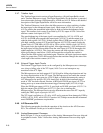
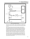
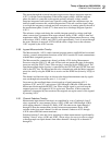
2-55. Ohms and RTDs
Resistance measurements are made using a ratio ohms technique, as shown in Figure 2-
5. A stable voltage source is connected in series with the reference resistor in A3Z4 and
the unknown resistor. Since the same current flows through both resistors, the unknown
resistance can be determined by multiplying the ratio of the voltage drops across the
reference and the unknown resistors by the known reference resistor value.
For the RTD, 300Ω, 3-kΩ, and 30-kΩ ranges, the ratio technique is implemented by
integrating the voltage across the unknown resistance for a fixed period of time and then
integrating the negative of the voltage across the reference resistance for a variable time
period. In this way, each minor cycle result gives the ratio directly.
For the 300-kΩ, 3-MΩ, and 10-MΩ ranges, the ratio is determined by performing two
separate voltage measurements in order to improve noise rejection. One fixed-period
integration is performed on the voltage across the unknown resistance, and the second
integration is performed on the voltage across the reference resistance. The ratio of the
two fixed-period voltge measurements is then computed by Microcontroller A3U9. The
resistance measurement result is determined when A3U9 multiplies the ratio by the
reference resistance value.