


Introduction and Specifications
Specifications
1
1-15
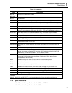
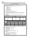
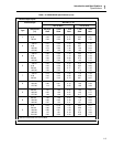
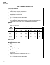
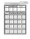
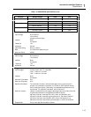
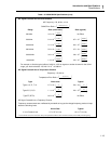
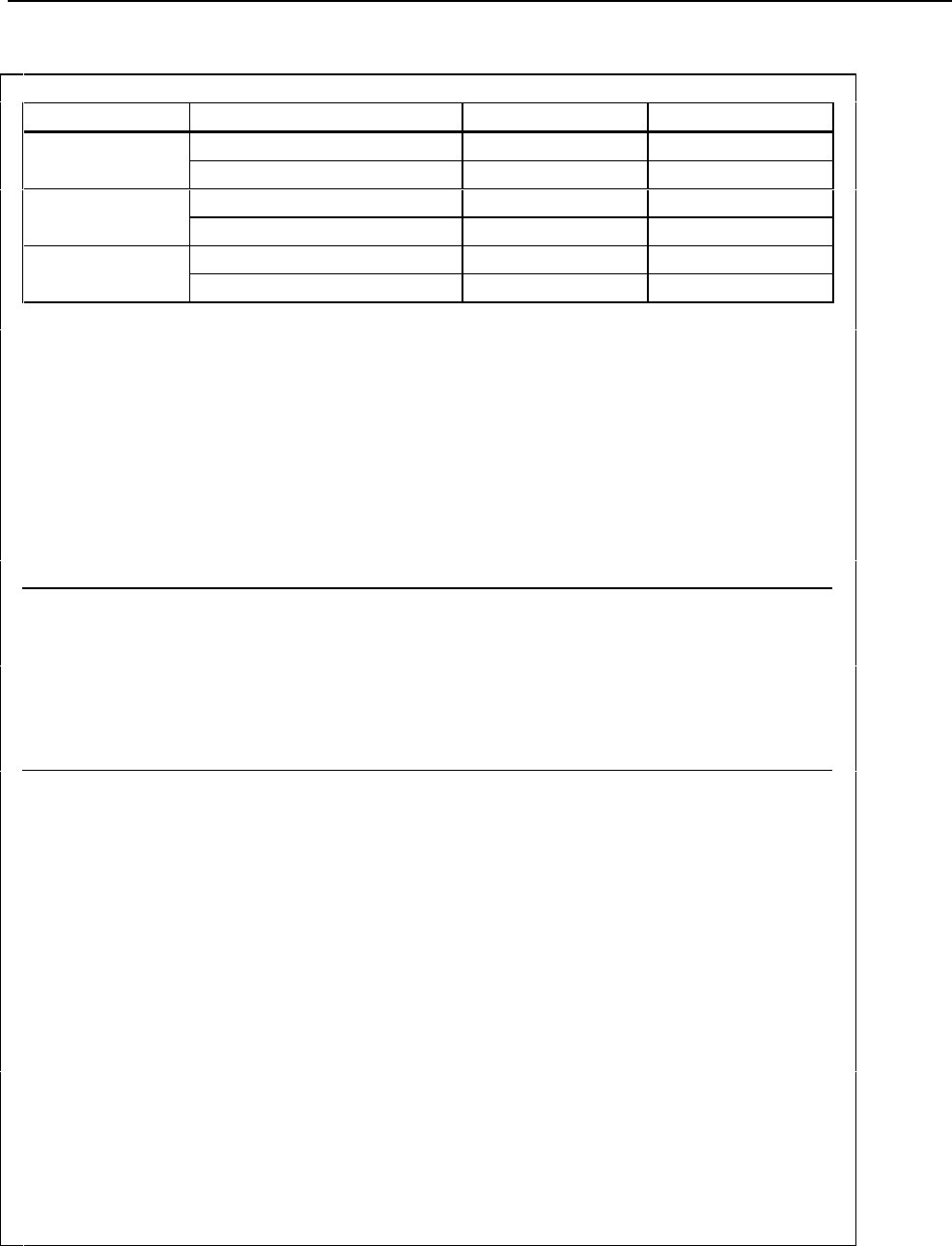
Table 1-3. 2620A/2625A Specifications (cont)
Maximum Autoranging Time (Seconds per Channel)
Function Range Change Slow Fast
VDC 300 mV to 150V 0.25 0.19
150V to 300 mV 0.25 0.18
VAC 300 mV to 150V 1.40 1.10
150V to 300 mV 1.40 1.10
Ohms 300Ω to 10.0 MΩ 1.70 0.75
10.0 MΩ to 300Ω 1.70 0.60
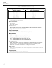
Totalizing Inputs
Input Voltage 30V maximum
-4V minimum
2V peak minimum signal
Isolation None
dc-coupled
Threshold 1.4V
Hysteresis 500 mV
Input Debouncing None or 1.66 ms
Rate 0 to 5 kHz with debouncing off
Maximum Count 65,535
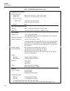
Digital Inputs
Input Voltage 30V maximum
-4V minimum
Isolation None
dc-coupled
Threshold 1.4V
Hysteresis 500 mV
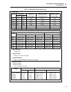
Trigger Inputs
Input Voltages contact closure and TTL compatible
"high" = 2.0V min, 7.0V max
"low" = -0.6V min, 0.8V max
Isolation None
dc-coupled
Minimum Pulse Width 5 µs
Maximum Frequency 5 Hz
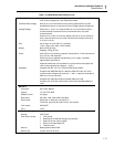
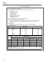
Specified Conditions The instrument must be in the quiescent state, with no interval scans in
process, no commands in the queue, no RS-232 or IEEE interface activity,
and no front panel activity if the latency and repeatability performance is to
be achieved. For additional information, refer to Section 5.
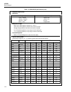
Maximum Latency Latency is measured from the edge of the trigger input to the start of the first
channel measurement for the Specified Conditions (above).
480 ms for fast rate, scanning DCV, ACV, ohms, and frequency only
550 ms for fast rate, scanning any thermocouple or 100 mV dc channels
440 ms for slow rate, scanning DCV, ACV, ohms, and frequency only
890 ms for slow rate, scanning any thermocouple or 100 mV dc channels
Repeatability 3 ms for the Specified Conditions (above)