


IEEE-488 Option -05
General Maintenance
7
7-5
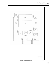
7-7. IEEE-488 Transceivers/Connector
The IEEE-488 Transceivers (A5U2 and A5U3) are octal transceivers that are specifically
designed to exhibit the proper electrical drive characteristics to meet the IEEE-488
standard. These transceivers are configured to match the control signals available on the
IEEE-488 Controller. Assuming that A5U1-33 is always high, Table 7-2 describes the
transceiver direction control. The IEEE-488 Transceivers connect to a 24-position
connector (A5J2), which mates with the ribbon cable leading to the IEEE-488 connector
mounted at the rear of the instrument chassis.
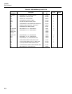
Table 7-2. IEEE-488 Transceiver Control
TRANSCEIVER TE = 0 (LISTENER) TE = 1 (TALKER)
DI01..DI08
SRQ
ATN
EOI
-
DAV
NRFD
NDAC
IFC
REN
Receiver
Transmitter
Receiver
Receiver
Receiver
Receiver
Transmitter
Transmitter
Receiver
Receiver
Transmitter
Transmitter
Receiver
Receiver (ATN = 0)
Transmitter (ATN = 1)
Transmitter
Receiver
Receiver
Receiver
Receiver
7-8. General Maintenance
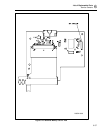
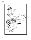
7-9. Removing the IEEE-488 Option
Remove the instrument cover as shown in Figure 7-1. Then remove the IEEE-488 Option
with the following procedure:
Note
Parts referenced by letter (e.g., A) are shown in Section 3 (Figure 3-4.)
1. From the bottom of the instrument, locate the IEEE-488 PCA (N). This pca is
connected to the front of Main PCA, with a ribbon cable (O) leading across both
pca’s to the Rear Panel. Refer to Figure 7-1.
2. Use needle nose pliers to disconnect the 24-line cable assembly at the IEEE-488
PCA, alternately pulling on each end of the cable connector. Leave the other end of
this cable attached to its Rear Panel connector.
3. Remove the 6-32, 1/4-inch panhead Phillips screw (P) securing the IEEE-488 PCA.
See Figure 7-1.
4. Disengage the IEEE-488 PCA by sliding it away from the Main PCA.