


HYDRA
Service Manual
2A-28
A3U8 switch S2, and the LO SENSE path of A3R35 and Analog Processor switch S19.
Passive filtering is provided by A3C34, A3C27, and portions or all of the DC Filter
block.
The voltage across the reference resistor for the 300Ω and RTD, 3-kΩ, and 30-kΩ
ranges (the 1-kΩ, 10.01-kΩ, and 100.5-kΩ resistances in A3Z4, respectively) is
integrated for a variable period of time until the voltage across the integrate capacitor
reaches zero. For the 300Ω and RTD range, the reference resistor voltage is switched in
through Analog Processor switch S6 and applied to the A/D Converter by switch S8. For
the 3-kΩ range, switches S9 and S11 perform these functions, respectively. For the 30-
kΩ range, switches S13 and S14 are used. For all ranges, the voltage is routed through
A3R34 to the RRS input.
The reference resistor for the 300-kΩ, 3-MΩ, and 10-MΩ ranges is the 1-MΩ resistor in
A3Z4, which is selected by S15. The voltage across this reference is integrated during its
own minor cycle(s) and is switched to a passive filter and the A/D Converter by switches
S1 and S18.
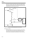
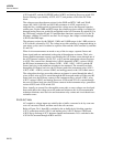
When 4-wire measurements are made on any of the six ranges, separate Source and
Sense signal paths are maintained to the point of the unknown resistance. The 4-wire
Source path measurement current is provided by the A3U8 ohms source through one of
the A3U8 internal switches (S6, S9, S13, or S15) and the appropriate reference resistor
in A3Z4. The current flows through relay A3K16, thermistor A3RT1, resistor A3R10,
the HI Source instrument relay contacts (A3K1 - A3K3, A3K5 - A3K14), and the HI
Source lead wire, to the unknown resistance to be measured. The current flows back
through the LO Source lead wire, the LO Source path of the instrument relays (A3K1 -
A3K3, A3K5 - A3K14), resistor A3R43, and analog ground, to the A3U8 ohms source.
The voltage that develops across the unknown resistance is sensed through the other 2
wires of the 4-wire set. HI is sensed through the HI Sense path made up of the users HI
Sense lead wire, the HI Sense contacts in the instrument relays, resistor A3R11, relay
A3K17, resistor A3R42, and Analog Processor A3U8 switch S2. LO is sensed through
the users LO Sense lead wire, the LO Sense contacts in the instrument relays, protection
resistor A3R35, and A3U8 switch S19.
Since virtually no current flows through the sense path, no error voltages are developed
that would add to the voltage across the unknown resistance; this 4-wire measurement
technique eliminates user lead-wire and instrument relay contact and circuit board trace
resistance errors.
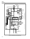
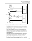
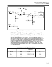
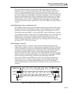
2A-55. AC Volts
AC-coupled ac voltage inputs are scaled by the ac buffer, converted to dc by a true rms
ac-to-dc converter, filtered, and then sent to the a/d converter.
Refer to Figure 2A-6. Input HI is switched to the ac buffer by dc-blocking capacitor
A3C31, protection resistor A3R11, and latching relay A3K15. Resistor A3R44 and
A3K15 act to discharge A3C31 between channel measurements. LO is switched to the
A3U8 A/D Converter through A3R34 and S18.