


Diagnostic Testing and Troubleshooting (2635A)
Calibration Failures
5A
5A-27
2. Wait a moment for the instrument to beep, then release SHIFT. The entire display
will now stay on until you are ready to deactivate it.
3. At the end of the activation period, press any button on the front panel; the
instrument resumes the mode in effect prior to the power interruption (Active or
Inactive.)
5A-20. Calibration Failures
5A-21. Introduction
Calibration of Hydra through the computer interface is described in Section 4 of this
manual. Generally, a calibration failure is indicated by a Device Dependent Error and a
"!>" prompt after a CAL_STEP? command if the RS-232 interface is being used. This
occurs if the analog input varies from what the instrument expects to see by more than
±5% or ±15%, depending on the calibration step.
Before suspecting a fault with Hydra, verify that the calibration is being conducted
properly.
• Check the connections between the source and the instrument. Are allthe
connections in place?
• Check the output of the calibration source. Does it equal the valuecalled for by this
calibration step?
• Check the calibration source. Is it in operate mode? Has it revertedto standby?
If a calibration step has failed, Hydra remains on that step so that the output from the
calibration source may be corrected or the calibration reference value (CAL_REF) being
used by Hydra may be changed if it was improperly entered. The calibration step may be
repeated by sending the CAL_STEP? command to Hydra again.
Calibration of Hydra utilizes a simple "calibration by function" approach. If you suspect
calibration errors, but the instrument does not exhibit the symptoms mentioned above,
verify that you are observing the following calibration rules:
• Independent calibration of any function results in the storage ofcalibration constants
for that function only.
• Once calibration is begun, all steps for that function must becompleted before the
calibration constants are stored. If all stepsare not completed and the procedure is
terminated, no constants forthat function are stored; only calibration constants for
previouslycompleted functions are stored.
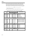
5A-22. Calibration-Related Components
If the calibration setup is correct, a faulty component within Hydra may be causing the
failure. Each measurement function depends on a combination of components in and
around the Analog Measurement Processor (A3U8).
RMS Converter A3U6
AC Buffer A3U7
Zener Reference A3VR1
Divider Network (DC/Ohms) A3Z4
Integrate Resistors, Reference Divider A3Z2
AC Divider Network A3Z3
RMS Converter Network A3Z1