


Diagnostic Testing and Troubleshooting (2620A/2625A)
Digital Kernel Troubleshooting
5
5-19
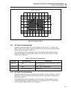
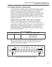
5-14. Digital Kernel Troubleshooting
At power-up, if the display does not light or lights up and fails to report errors or begin
operation, use the following troubleshooting procedures.
First check the state of SWR1 (A1U4-21). If this status line is less than 0.8V, basic
processor operation is intact. Examining SWR2 through SWR5 (A1U4-22 through -25,
respectively) should indicate how far the software progressed before finding an error. If
the state of SWR1 is not less than 0.8V, the problem may be in the 6303Y
Microprocessor (A1U4), the ROM or NVRAM decode circuitry (A1U10 and A1U21),
the ROM (A1U8) or NVRAM (A1U3), or the address/data lines among these parts.
Note
The functions of SWR1 through SWR5 as power-upstatus lines persist for
only 3 to 4 seconds. Thesefunctions end when the keyboard scanner
beginsoperation (if it can). Extremely difficult casesmay require the use of
an oscilloscope triggered onthe falling edge of SWR1 to examine the states
ofSWR2 through SWR5.
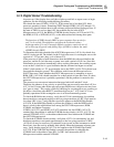
To determine the relative health of the 6303Y Microprocessor (A1U4), first check for a
valid E clock at pin 68. The default for the E clock after reset is a rectangular wave with
a period of 1.221 µs and a duty cycle of about 67%.
If the processor is able to fetch instructions from the ROM, the software initializes the
processor, and the E clock becomes a square wave with a period of 0.814 us. Since this
initialization occurs almost immediately with a working instrument, the resulting square
wave on the E clock line is a good indication that the software has begun to execute.
If the E clock remains a 1.221 µs rectangular wave, the SWR2 (A1U4-22) keyboard scan
line might be shorted to ground. This condition would cause the Microprocessor to
HALT after reset. Check whether the 6303Y Microprocessor is attempting to access
ROM; LIR* (A1U4-64) should transition for a short period of time after reset. If it does,
the 6303Y Microprocessor is probably operational, and the problem is external to the
processor.
The processor can execute an instruction that stops both itself and the E clock.
Therefore, the absence of any activity on pin 68 does not necessarily mean that A1U4 or
A1Y1 is bad. If some other failure prevents proper ROM access, the processor may have
just "gone to sleep". This can be verified by checking for a rectangular wave occurring at
pin 68 for a short time after RESET* transitions high on pin 7. A1U4 and A1Y1 are
probably operational if this rectangular wave is at least momentarily present.
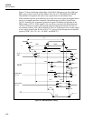
To check the ROM decode circuitry, verify that A1U10-6 is transitioning low and that
these transitions correspond roughly to the low-going transitions of LIR*. Pin 6 must be
low when LIR* is low. Verify that this signal also appears at the ROM Chip Enable,
A1U8-20. If the ROM Chip Enable is present, the problem is with the ROM itself or
there is a fault in the address/data lines among the 6303Y Microprocessor, ROM,
NVRAM, and Option Connector.
If SWR1 (A1U4-21) and SWR2 (A1U4-22) transition low, but SWR3 (A1U4-23)
remains high, the problem is with the NVRAM decode circuitry (A1U15, A1U21), the
external NVRAM (A1U3), or the address/data/control lines between the NVRAM and
the 6303Y Microprocessor.
To check the NVRAM decode circuitry, verify that A1U21-6 is transitioning low and
that these transitions correspond approximately to the low-going transitions of WR*
(A1U4-66). It may be necessary to continually reset (power on) the instrument to check
these lines, since the activity probably halts quickly when the instrument software goes
awry. Verify that the signal on A1U21-6 also appears at the NVRAM Chip Enable,
A1U3-20. If the NVRAM Chip Enable is present, the problem is with either the
NVRAM itself or the address, data, RD*, or WR* lines between the 6303Y
Microprocessor and the external NVRAM.