


Diagnostic Testing and Troubleshooting (2635A)
Introduction
5A
5A-3
5A-1. Introduction
Hydra provides error code information and semi-modular design to aid in
troubleshooting. This section explains the error codes and describes procedures needed
to isolate a problem to a specific functional area. Finally, troubleshooting hints for each
functional area are presented.
But first, if the instrument fails, check the line voltage fuse and replace as needed. If the
problem persists, verify that you are operating the instrument correctly by reviewing the
operating instructions found in the Hydra Users Manual.
Warning
Opening the case may expose hazardous voltages. Always
disconnect the power cord and measuringinputs before
opening the case. And remember that repairs or servicing
should be performed only by qualified personnel.
Required equipment is listed in Section 4 of this manual.
Signal names followed by a ’*’ are active (asserted) low. Signal names not so marked are
active high.
5A-2. Servicing Surface-Mount Assemblies
Hydra incorporates Surface-Mount Technology (SMT) for printed circuit assemblies
(pca’s). Surface-mount components are much smaller than their predecessors, with leads
soldered directly to the surface of a circuit board; no plated through-holes are used.
Unique servicing, troubleshooting, and repair techniques are required to support this
technology. The information offered in the following paragraphs serves only as an
introduction to SMT. It is not recommended that repair be attempted based only on the
information presented here. Refer to the Fluke "Surface Mount Device Soldering Kit" for
a complete demonstration and discussion of these techniques. (In the USA, call 1-800-
526-4731 to order.)
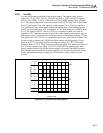
Since sockets are seldom used with SMT, "shotgun" troubleshooting cannot be used; a
fault should be isolated to the component level before a part is replaced. Surface-mount
assemblies are probed from the component side. The probes should make contact only
with the pads in front of the component leads. With the close spacing involved, ordinary
test probes can easily short two adjacent pins on an SMT IC.
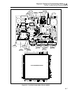
This Service Manual is a vital source for component locations and values. With limited
space on the circuit board, chip component locations are seldom labeled. Figures
provided in Section 6 of this manual provide this information. Also, remember that chip
components are not individually labeled; keep any new or removed component in a
labeled package.
Surface-mount components are removed and replaced by reflowing all the solder
connections at the same time. Special considerations are required.
• The solder tool uses regulated hot air to melt the solder; there isno direct contact
between the tool and the component.