


Diagnostic Testing and Troubleshooting (2620A/2625A)
Variations in the Display
5
5-25
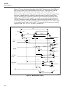
5. Verify that the DISRX signal (A2U1-39) goes low after RESET (A2U1-1) goes low.
If this sequence does not occur, communication to the Microprocessor is held off
with the DISRX signal high. If DISRX stays high but is not shorted to VCC, A2U1
must be faulty.
6. Verify activity for both the DISTX and DSCLK signals. These signals are driven by
the Microprocessor and must be transitioning for the Display Controller to receive
commands from the Microprocessor.
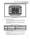
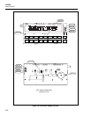
7. If all segments of a particular digit do not turn on at power-up, the grid drive from
A2U1 may not be connected properly to A2DS1. Grids are numbered from 10 to 0
(left to right as the display is viewed). For a digit to be enabled, the respective grid
drive signals (GRID(10:0)) must be at approximately VCC (4.85 to 5.35V dc.) For a
digit to be disabled, the drive must be at VLOAD (-28.5 to -32.0V dc.)
8. If a segment under each of several (or all) grids fails to be turned on (or off)
properly, one of the anode drive signals may not be connected properly from A2U1
to A2DS1. When an anode signal is at VCC, and a grid signal is at VCC, the
corresponding segment on the display is illuminated.
9. If the Microprocessor has difficulty recognizing front-panel button presses, the
switch scanning signals (SWR1 through SWR6, A1U4-21 through -26, respectively)
should be checked. When no switch contacts are being closed, the switch scanning
lines should have about 20 kΩ of resistance between each other (through two 10-kΩ
pullup resistors to VCC). Unless one of the switches is closed, none of the switch
scanning lines should be shorted directly to GND at any time.
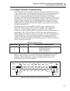
5-19. Variations in the Display
Note
The following procedure will not work with Hydra’s Mainframe Firmware
version 5.5.
Under normal operation, the display presents various combinations of brightly and dimly
lit annunciators and digits. However, you may encounter other, random irregularities
across different areas of the display under the following circumstances:
• After prolonged periods of displaying the same information.
• If the display has not been used for a prolonged period.
This phenomenon can be cleared by activating the entire display and leaving it on
overnight (or at least for several hours). Use the following procedure to keep the display
fully lit:
1. With power OFF, press and hold SHIFT, then press power ON.
2. Wait a moment for the instrument to beep, then release SHIFT. The entire display
will now stay on until you are ready to deactivate it.
3. At the end of the activation period, press any button on the front panel; the
instrument resumes the mode in effect prior to the power interruption (Active or
Inactive.)