


HYDRA
Service Manual
2A-12
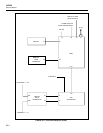
The Microprocessor communicates to the Display Controller using a synchronous, three-
wire communication interface controlled by hardware in the Microprocessor.
Information is communicated to the Display Controller to display user interface menus
and measurement data. Details of this communication are described in the Display
Controller Theory of Operation in this section.
The Microprocess communicated to the Microcontroller on the A/D Converter PCA (via
the Serial Communication circuit) using an asynchronous communication channel at
4800 baud. Communication to the Microcontroller (A3U9) originates at A1U1-54.
Communication from the A/D’s Microcontroller to the Microprocessor appears at A1U1-
53. When there is no communication in progress between the Microprocessor and the
Microcontroller, both of these signals are high.
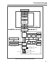
The Microprocessor uses another asynchronous communication channel to communicate
to external computing or modem equipment through the RS-232 interface. This interface
is described in detail in the RS-232 Interface Theory of Operation in this section.
The third asynchronous communication channel in the Microprocessor is connected to
the Option Interface (J1) but is not used in the instrument at this time.
The interrupt controller in the Microprocessor prioritizes interrupts received from
hardware devices both internal and external to the Microprocessor. Table 2A-1 lists
interrupt sources from highest to lowest priority.
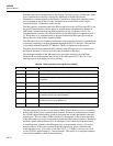
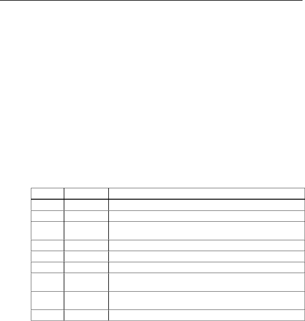
Table 2A-1. Microprocessor Interrupt Sources (2635A)
Pin Signal Name Description
A1U1-95 XTINT* External Trigger Interrupt (Highest Priority)
A1U1-96 CINT* Real-Time Clock Interrupt; once per second
A1U1-121 KINT* Keyboard Interrupt; interrupts on each debounced change of keyboard
conditions.
RS-232 Interface Interrupt; internal to the Microprocessor.
A/D Communication Interrupt; internal to the Microprocessor.
Timer Interrupt every 53.333 milliseconds; internal to the Microprocessor.
A1U1-119 MCINT* Memory Card Interface Interrupt; interrupts when a memory card is inserted,
removed, powered up or powered down.
Totalizer Interrupt; internal to the Microprocessor. Interrupts on totalizer
overflow from a count of 65535 to 0.
A1U1-97 OINT* Option Interface Interrupt; not currently used in this product.
The Microprocessor also has several internal DMA (Direct Memory Access) controllers
that are used by the serial communication channels. Each serial communication channel
has a DMA channel that handles character reception and another that handles character
transmission. The use of these DMA controllers is transparent to the external operation
of the Microprocessor, but it is important to understand that communication is handled at
hardware speeds without the need for an interrupt for each character being transferred.
A watchdog timer internal to the Microprocessor is programmed to have a 10-second
timeout interval. If the code executed by the Microprocessor fails to reinitialize the
watchdog timer every 10 seconds or less, then A1U1-117 (POR*) is driven low for 16
cycles of SCLK (approximately 1.3 microseconds). This results in a complete hardware
reset of the instrument, which restarts operation.