


HYDRA
Service Manual
5-6
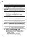
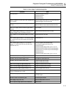
Table 5-1. Error Codes (cont)
Error Description
Error b A/D RAM test failure
Complementary patterns are alternately written to and read from each location of the 256 bytes of
RAM internal to the 6301Y Microcomputer (A3U9).
Error C A/D self test failed
The Analog Measurement Processor (A3U8) is programmed to do self test measurements.
5-4. General Troubleshooting Procedures
Hydra allows for some fault isolation using self-diagnostic routines and descriptive error
codes. However, these features are somewhat limited and do not provide in-depth
troubleshooting tools.
Hydra incorporates a semi-modular design; determining modules not related to a
problem constitutes the first step in the troubleshooting process.
As a first step, remove the IEEE-488 Option (if installed) from the Data Acquisition Unit
(2620A) or the Memory PCA from the Data Logger (2625A). Refer to Section 3 of this
manual for removal procedures. If removal of either of these assemblies results in
improved instrument operation, refer to Section 7 for IEEE-488 Option troubleshooting
or later in this section for Memory PCA troubleshooting.
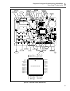
Measuring the power supplies helps to isolate a problem further. Refer to Table 5-2 and
Figure 5-1 for test point identification and readings. If power supply loading is
suspected, disconnect the Display PCA at A1J2. If this action solves the loading
problem, proceed to Display Assembly Troubleshooting elsewhere in this section.
Otherwise, refer to Power Supply Troubleshooting.
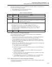
Table 5-2. Preregulated Power Supplies
PREREGULATED VOLTAGE MEASUREMENT POINTS RESULTING SUPPLY
-9.0V
-30V
+9.25V
-8.75V
A1CR13-2 to A1TP1
A1TP4 to A1TP1
A1CR5 cathode to A1TP30
A1CR7 anode and A1TP30
VEE
VLOAD
VDD, VDDR
VSS
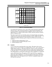
If the power supplies appear good, check the E clock signal to determine whether the
Main PCA or the Display PCA is causing the problem. A correct display depends on the
E clock signal. Missing segments, intensified digits, a strobing display, or a blank
display can be caused by a faulty E clock.
Use an oscilloscope to check for the E clock at Microprocessor A1U4, pin 68. Look for a
1.2288-MHz square wave that transitions from 0 to 5V dc (VCC).
• If this signal is present, the Display PCA is probably faulty. Referto Display
Assembly Troubleshooting elsewhere in this section.
• If the E clock is something other than a 1.2288-MHz square wave,isolate the digital
section of the Main PCA by disconnecting theDisplay PCA at J2. Then check the E
clock again, and refer to DigitalTroubleshooting elsewhere in this section for further
problemisolation.
Refer to the Schematic Diagrams in Section 8 during the following troubleshooting
instructions. Also, these diagrams are useful in troubleshooting circuits not specifically
covered here.