


HYDRA
Service Manual
2-30
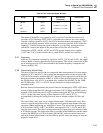
approximately 20 kΩ. Checking resistances between any two signals (SWR1 through
SWR6) verifies proper termination by resistor network A2Z1.
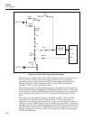
2-67. Display
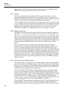
The custom vacuum-fluorescent display (A2DS1) comprises a filament, 11 grids
(numbered 0 through 10 from right to left on the display), and up to 14 anodes under
each grid. The anodes make up the digits and annunciators for their respective area of the
display. The grids are positioned between the filament and the anodes.
A 5.4V ac signal, biased at a -24V dc level, drives the filament. When a grid is driven to
+5V dc, the electrons from the filament are accelerated toward the anodes that are under
that grid. Anodes under that grid that are also driven to +5V dc are illuminated, but the
anodes that are driven to -30V dc are not. Grids are driven to +5V dc one at a time,
sequencing from GRID(10) to GRID(0) (left to right, as the display is viewed.)
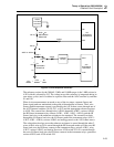
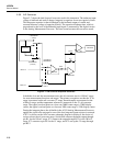
2-68. Beeper Drive Circuit
The Beeper Drive circuit drives the speaker (A2LS1) to provide an audible response to a
button press. A valid entry yields a short beep; an incorrect entry yields a longer beep.
The circuitry comprises a dual four-bit binary counter (A2U4) and a NAND gate (A2U6)
used as an inverter. One four-bit free-running counter (A2U4) divides the 1.2288-MHz
clock signal (E) from the microprocessor (A1U4) by 2 to generate the 614.4-kHz clock
(CLK1) used by the Display Controller. This counter also divides the 1.2288-MHz clock
by 16, generating the 76.8-kHz clock that drives the second four-bit binary counter
(A2U4).
The second four-bit counter is controlled by an open-drain output on the Display
Controller (A2U1-17) and pull-down resistor A2R1. When the beeper (A2LS1) is off,
A2U1-17 is pulled to ground by A2R1. This signal is then inverted by A2U6, with
A2U6-6 driving the CLR input high to hold the four-bit counter reset. Output A2U4-8 of
the four-bit counter drives the parallel combination of the beeper (A2LS1) and A2R10 to
ground to keep the beeper silent. When commanded by the Main Microprocessor, the
Display Controller drives A2U1-17 high, enabling the beeper and driving the CLR input
of the four-bit counter (A2U4-12) low. A 4.8-kHz square wave then appears at counter
output A2U4-8 and across the parallel combination of A2LS1 and A2R10, causing the
beeper to resonate.
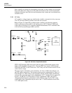
2-69. Watchdog Timer and Reset Circuit
This circuit provides active high and active low reset signals to the rest of the system at a
power-up or system reset if the Microprocessor does not communicate with the Display
Processor for a 5-second period. The Watchdog Timer and Reset Circuit comprises dual
retriggerable monostable multivibrator A2U5, NAND gates A2U6, diode A2CR3, and
various resistive and capacitive timing components.
At power-up, capacitor A2C3 begins to charge up through resistor A2R3. The voltage
level on A2C3 is detected by an input of Schmitt-Trigger NAND gate A2U6-12. The
output of this gate (A2U6-11) then drives the active high reset signal (RESET) to the rest
of the system. When the voltage on A2C3 is below the input threshold (typically +2.5V
dc) of A2U6-12, A2U6-11 is high. As soon as A2C3 charges up to the threshold of
A2U6-12, A2U6-11 goes low. The RESET signal drives NAND gate inputs A2U6-1 and
A2U6-2 to generate the active low reset signal (RESET*) at A2U6-3.
When the RESET signal transitions from high to low (A2U5-1), the Watchdog Timer is
triggered initially, causing A2U5-13 to go high. This half of the dual retriggerable
monostable multivibrator uses timing components A2R2 and A2C2 to define a nominal