


Chapter 9 Monitoring BCM50 Status and Metrics 241
BCM50 Administration Guide
Table 64 describes the settings.
3 Configure the polling interval.
PVQM alarms
If an alarm is generated to report a threshold violation, additional information is included in
the alarm to indicate the source of the alarm and provide other troubleshooting information.
Table 63 lists the abbreviations used in the alarm text to present this additional information.
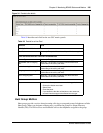
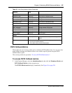
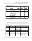
Table 62 PVQM threshold settings
Metric Description Value Range
Default Value
for Warning
thresholds
Default Value
for
Unacceptable
thresholds
Packet Loss Rate The fraction of RTP data
packets from the source lost
since the beginning of the call,
expressed as a percentage.
0-100 1% 5%
Inter-arrival Jitter The inter-arrivak time of
incoming RTP packets, as
defined in RFC 1889.
Expressed in milliseconds.
0-1000 50 ms 500 ms
RTCP Round Trip
Delay
The round trip time of
incoming RTP packets, as
defined in RFC 1889.
Measured in milliseconds.
0-1000 300 ms 500 ms
Listening R Factor A scale from 0 (lowest quality)
to 100 (highest quality)
according to ITU-T G.107.
0-100 65 n/a
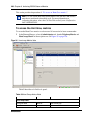
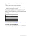
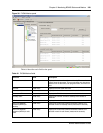
Table 63 PVQM alarm information
Abbreviation Attribute Value Description
cT codec type alphanumeric Vocoder type used on this call
eT endpoint type S or D S indicates softclient
D indicates desktop
nLR network loss rate percentage, scaled by
256 (e.g. 354 = 1.4%)
Rate of network packet loss
dR average discard rate percentage, scaled by
256
Average rate of discards due to jitter
bD burst loss density percentage, scaled by
256
Density of lost and discarded
packets during burst periods
bL burst length milliseconds Average length of bursts
gD gap loss density percentage, scaled by
256
Density of lost and discarded
packets during gap periods
gL average length of gap milliseconds average length of gap